Surface-micromachined micro-magnetic undulator

a surface-micromachined, undulator technology, applied in the field of undulators, can solve the problems of undulators occupying a volume greater than one cubic meter, weighing more than 10 kilograms, and requiring significant structural support, and achieve the effect of increasing the current density

Active Publication Date: 2014-10-09
RGT UNIV OF CALIFORNIA
View PDF3 Cites 5 Cited by
  • Summary
  • Abstract
  • Description
  • Claims
  • Application Information

AI Technical Summary

Benefits of technology

[0017]Certain embodiments provide an undulator with a relatively enhanced current density via a low thermal path including a substrate and optionally a metal base layer. Certain embodi...

Problems solved by technology

Further, the intense fields developed by the close spacing of 1 T to 10 T permanent magnets in conventional permanent magnet undulators generate enormous forces that require significant structural support.
Such structural support may result in undulators that occupy a volume of greater than one cubic meter, and may weigh more than 10,000 kg.
Further, the magnetic fields tend to be non-uniform.
Such types of undulators are too large, heavy, and expensive for many types of applications.
Certain other undulator designs use expensive, hand assembled 100 micron scale wax-bound powder permanent magnets, magnetic fields induced by a high power laser, or betatron oscillators which use laser-plasma Wakefield accelerators to extract MeV energy photons from GeV energy electrons.
Conventional wax-bound hard micro-magnets typically have not been scaled below 100 microns, must be hand assembled, and have poor field uniformity due to limitations in the NiFeB microstructural grain size, the magnetic domain size, and thermal stability of the materia...

Method used


Image

  • Surface-micromachined micro-magnetic undulator
  • Surface-micromachined micro-magnetic undulator
  • Surface-micromachined micro-magnetic undulator

Examples


Embodiment Construction

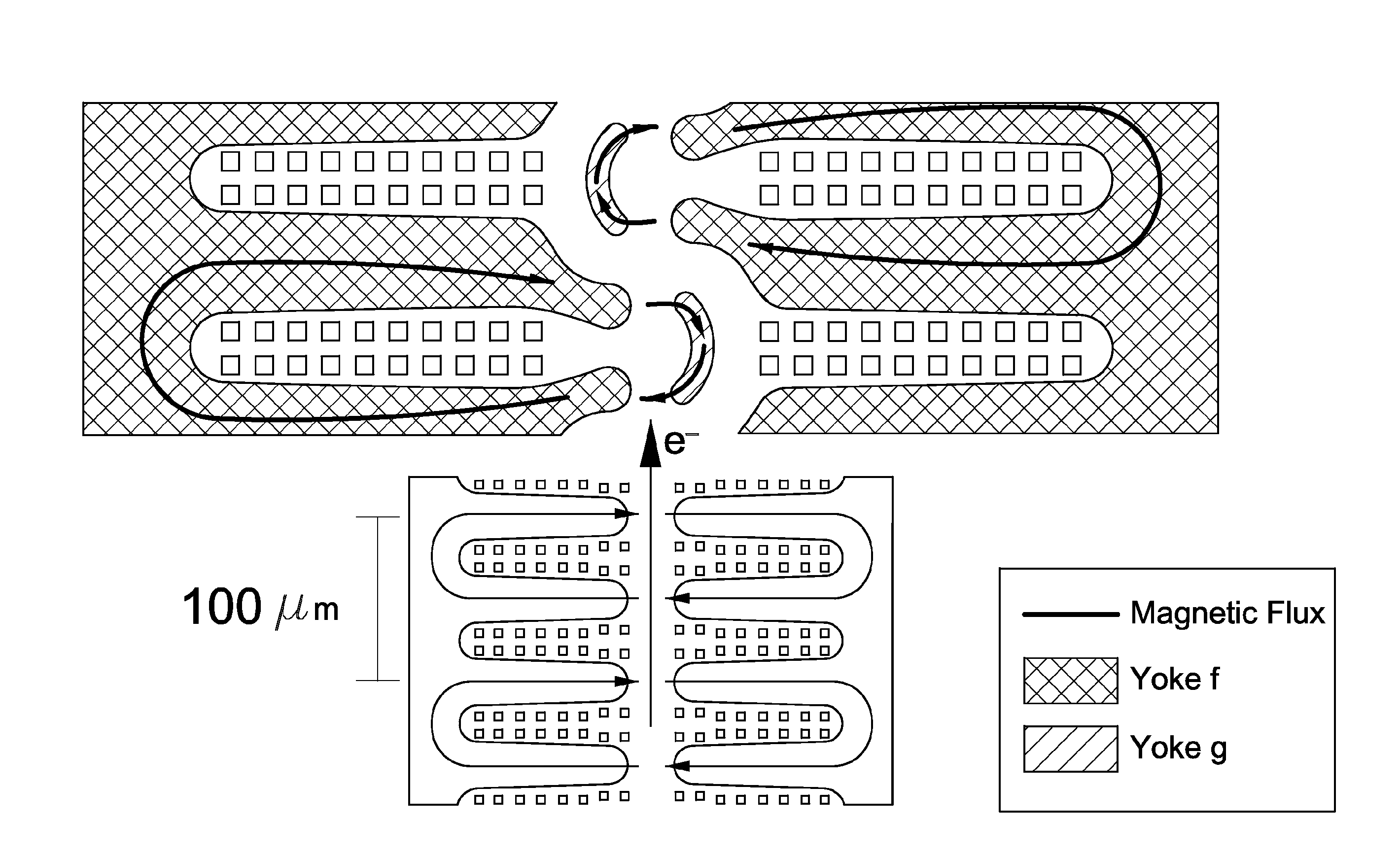
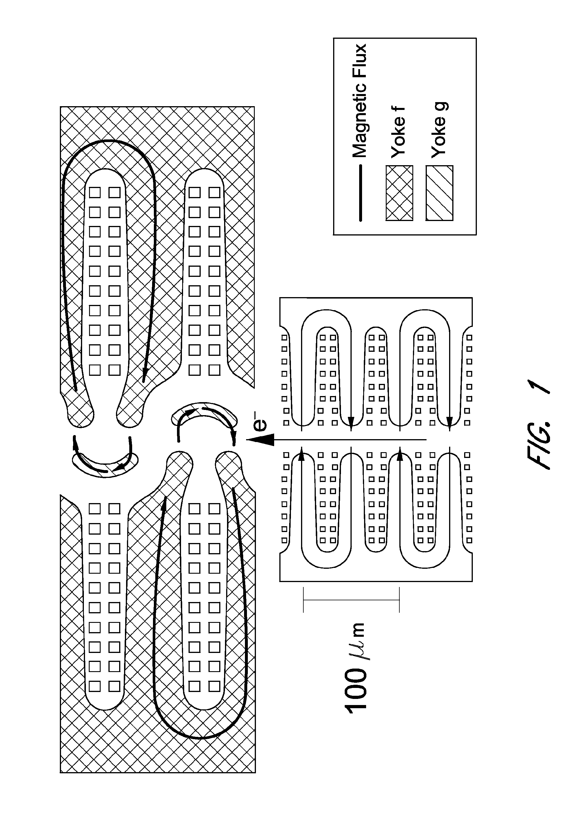
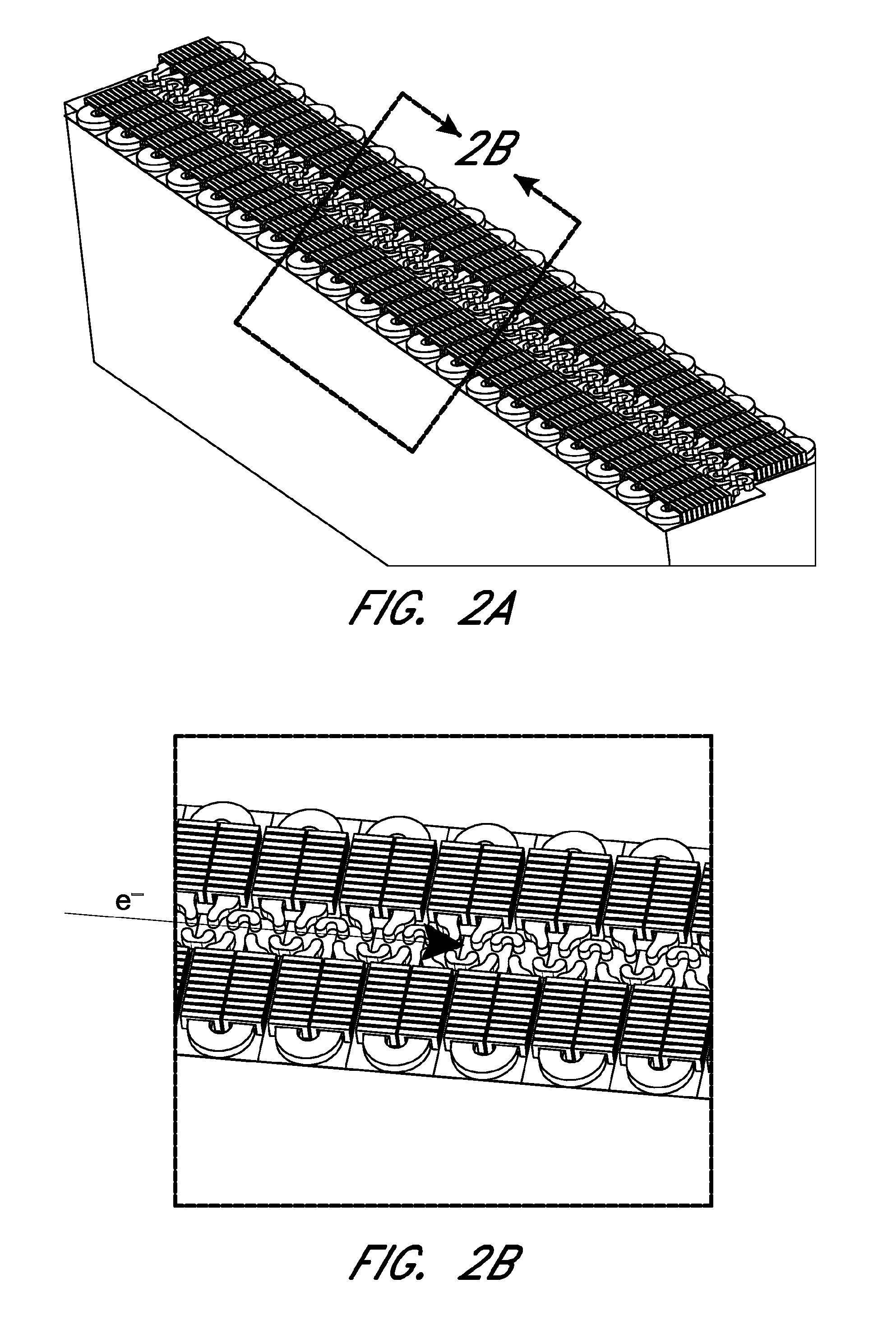
[0032]As is well known, free electron lasers (FEL) use a relativistic electron beam as the lasing medium which moves through a magnetic structure. In particular, in a FEL, a beam of electrons is accelerated to almost the speed of light. The beam passes through an oscillator / undulator (sometimes referred to as a “wiggler”), which generates a periodic transverse magnetic field using an arrangement of magnets with alternating poles within an optical cavity along the electron beam path. The undulator may cause, at least in part, the beam electrons to follow a sinusoidal path.

[0033]However, as discussed above, conventional undulators suffer from many deficiencies, including size, weight, power requirements, difficulty of manufacturer, insufficiently narrow spectral output, etc. Some or all of these deficiencies are overcome by certain embodiments described herein.

[0034]Certain embodiments provide a compact, low-powered micromachined undulator, which may be a soft-magnetic undulator havin...


PUM


Abstract

Various embodiments of undulators, methods of fabricating undulators, and systems incorporating undulators are described. Certain embodiments provide a compact, electromagnetic undulator. The undulator may comprise a substrate and one or more electromagnets, which may be formed on the substrate. Certain embodiments have a period not greater than about 5 mm. The undulator may be operatively coupled with a particle accelerator to provide a free electron laser system.

Description

CROSS-REFERENCE TO RELATED APPLICATIONS[0001]This application is a U.S. National Phase of International Application No. PCT / US2012 / 064542, filed Nov. 9, 2012, which claims priority from U.S. Patent Application No. 61 / 558,944, filed Nov. 11, 2011, the contents of which are incorporated herein by reference in their entirety.STATEMENT REGARDING FEDERALLY SPONSORED R&D[0002]This invention was made with Government support under N660001-12-1-4209, awarded by the Space and Naval Warfare Systems Command. The Government has certain rights in the invention.PARTIES OF JOINT RESEARCH AGREEMENT[0003]Not applicable.BACKGROUND OF THE INVENTION[0004]1. Field of the Invention[0005]The present invention relates to an undulator for use with a free-electron laser system, and in particular, to an electro-magnetic undulator and processes for fabricating the same.[0006]2. Description of the Related Art[0007]Conventional devices used for the decelerator / interaction region of a collimated X-Ray free electro...

Claims


Application Information

Patent Timeline
IPC IPC(8): H05H7/04H01F7/06H01S3/09
CPCH01S3/0903H01F7/06H05H7/04H01S1/005H01S3/0959
Inventor HARRISON, JEREJOSHI, ABHIJEET
Owner RGT UNIV OF CALIFORNIA
Why Eureka
Try Eureka