In-vehicle engine control device and control method thereof

a technology of in-vehicle engine and control device, which is applied in the direction of electrical control, process and machine control, etc., can solve the problems of inability to suppress the increase in temperature of inductive element, difficulty in detecting peak current detection error, and fluctuation of fuel injection characteristic, etc., to achieve stable fuel injection characteristic, easy to variably set, and high-speed control burden

Active Publication Date: 2014-10-23
MITSUBISHI ELECTRIC CORP
View PDF0 Cites 27 Cited by
  • Summary
  • Abstract
  • Description
  • Claims
  • Application Information

AI Technical Summary

Benefits of technology

[0013]A first object of this invention is to provide an in-vehicle engine control device including a boosting circuit unit which can provide a stable fuel injection characteristic, suppress a temperature increase of a boosting inductive element, allow a target value of a driving current of the boosting inductive element and a target value of a boosted high voltage which is a charged voltage of a high-voltage capacitor to be easily variably set, and does not give a high-speed control burden to a microprocessor. A second object of this invention is to provide an in-vehicle engine control method capable of suppressing a temperature increase by reducing a driving current of a boosting inductive element to be as small as possible according to actual driving circumstances, and reliably achieving a targeted boosted high voltage until the next fuel injection is performed.
[0016]The in-vehicle engine control device according to the aspect of this invention includes a solenoid valve driving control circuit unit for a plurality of electromagnetic coils for driving solenoid valves, a boosting circuit unit, an arithmetic and control circuit unit, and an injection control circuit unit. The arithmetic and control circuit unit includes a multi-channel A / D converter that is operated at low speed, cooperating with a microprocessor, a high-speed A / D converter with a plurality of channels, and a boosting control circuit portion. The boosting control circuit portion includes a plurality of numerical value comparators and a logical circuit portion. The arithmetic and control circuit unit is divided into a data processing function of setting numerical values of a target supply current for a boosting inductive element of the boosting circuit unit and a target boosted voltage of a high-voltage capacitor charged to a boosted voltage, and converting numerical values of an inductive element current and boosted detection voltage, and a digital logic control function of performing negative feedback control such that a target value as which the numerical value is set is the same as a monitored present value into which the numerical value is converted. Therefore, there is an effect in which the microprocessor can easily adjust set data which is a control constant value by using a set register, and the boosting control circuit portion controls opening and closing of a boosting opening and closing element which performs opening and closing operations at a high frequency so as to alleviate a high-speed control burden on the microprocessor, improves control accuracy of fuel injection control by adjusting the boosted high voltage, and adjusts an inductive element current suitable for a targeted boosted high voltage, thereby performing control so as to obtain a boosted high voltage which constantly varies within a predetermined period.
[0017]In addition, in the in-vehicle engine control method according to another aspect of this invention, recharging of the high-voltage capacitor is completed after the electromagnetic coils for fuel injection are rapidly excited, a charging allowance time until the next rapid excitation is performed is measured, and a target higher-side current for the inductive element is adjusted so as to be increased or decreased according to a degree of the present charging allowance time. Therefore, there is an effect in which, in a case where the engine speed is low and a fuel injection interval Ts from the previous fuel injection to the next fuel injection is long, the high-voltage capacitor is not required to be rapidly charged, and thus a target higher-current is suppressed so as to suppress power consumption in the boosting circuit unit, thereby reducing a temperature increase of circuit parts. In addition, since a charging necessary time Tc of the high-voltage capacitor fluctuates so as to increase or decrease in inverse proportion to a power supply voltage of the in-vehicle battery, and fluctuates depending on a temperature of the inductive element, and the fuel injection interval Is fluctuates in inverse proportion to the engine speed, a target higher-side current can be accurately set by measuring the charging necessary time Tc or the charging allowance time Tb as learning information.

Problems solved by technology

Therefore, the fuel injection valve control device has a feature in which it is difficult for a detection error of a peak current to occur.
However, when there is an error in arrival time of a peak value even if the peak value is the same, there is a problem in that a fuel injection characteristic fluctuates.
On the other hand, in PTL 1, a transistor MN1 which intermittently excites the boosting inductive element is driven so as to be opened and closed in response to a PWM signal with a variable duty cycle which is generated by the microcomputer 12, and thus there is a problem in that a current flowing through the boosting inductive element varies depending on a fluctuation in a power supply voltage or a fluctuation in a resistance of the inductive element caused by temperature even in the same on and off ratio, a boosted high voltage fluctuates even if an on and off ratio is constant, and thereby the fuel injection characteristic fluctuates.
In addition, in a case where engine speed is low and there is sufficient allowance time for charging, it is effective to increase a frequency of the PWM signal by decreasing an on and off ratio, but this is difficult since a driving current of the inductive element is not detected in the fuel injection valve control device disclosed in PTL 1, and thus there is a problem in that an increase in temperature of the inductive element cannot be suppressed.
Therefore, there is a problem in that the fuel injection characteristic fluctuates depending on a temperature fluctuation of the electromagnetic solenoid.
On the other hand, in PTL 2, when a power supply voltage or engine speed is lowered, a temperature increase of the boosting power supply device is intended to be suppressed by decreasing the higher-side current threshold value iH and increasing the lower-side current threshold value iL so as to reduce an increase range of the driving current Is; however, in relation to the magnitude of the driving current, not only a power supply voltage but also an influence of a resistance variation caused by temperature of the inductive element is a major fluctuation factor, and it is problematic to set an increase range of the driving current Is by using, for example, a two-element map formed only by the power supply voltage and the engine speed.
Therefore, there is a problem in that heat generation of the inductive element cannot be effectively suppressed unless an increase range of the driving current is changed based on a power supply voltage, engine speed, and temperature (resistance) of the inductive element.
Further, as shown in FIG. 11, even if an increase range is set without steps, it is difficult how to determine an increase range of the driving current Is, and if a boosted high voltage is to be variably adjusted, the difficulty thereof further increases.

Method used


Image

  • In-vehicle engine control device and control method thereof
  • In-vehicle engine control device and control method thereof
  • In-vehicle engine control device and control method thereof

Examples


embodiment 1

(3) Main Points and Features of Embodiment 1

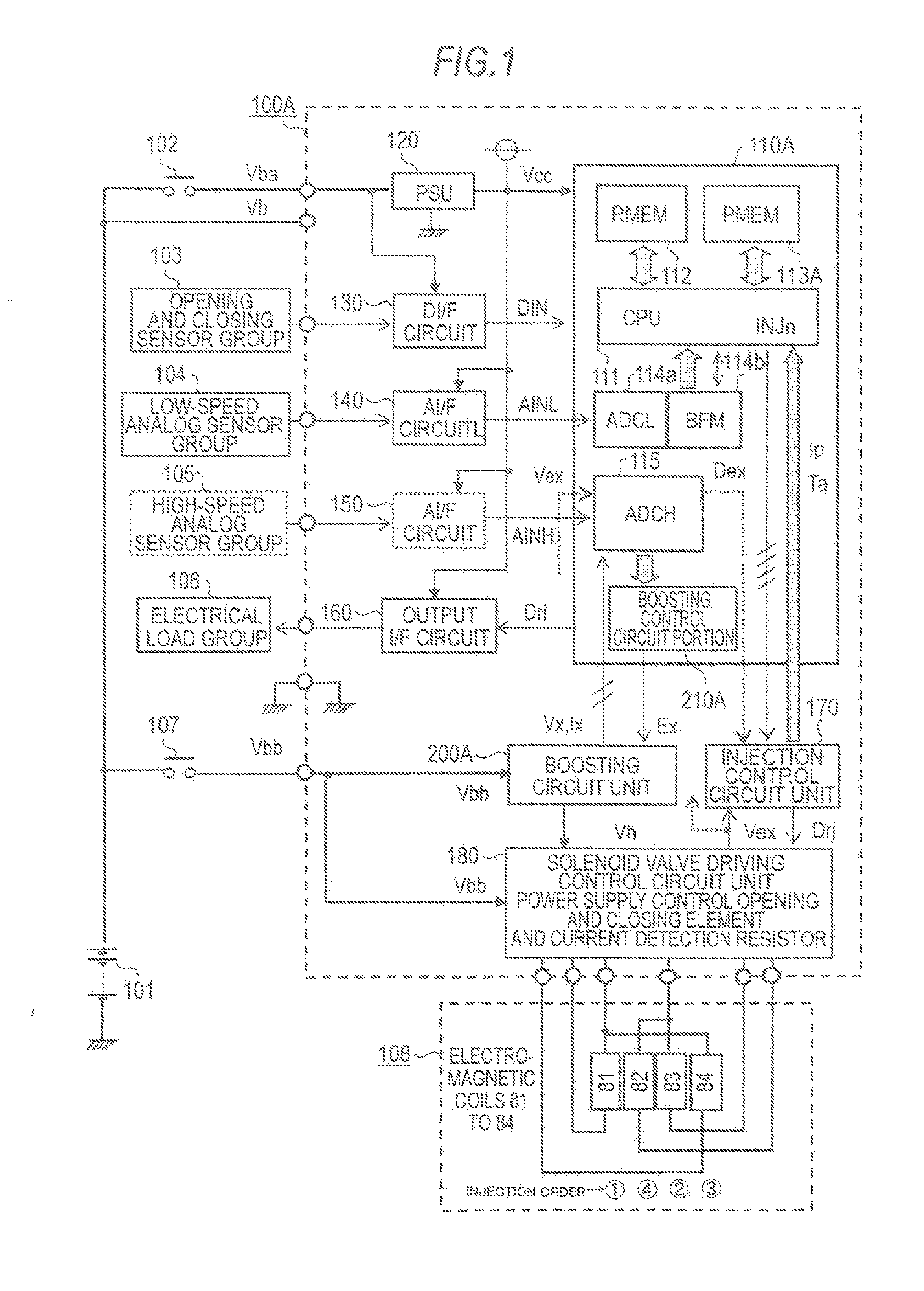
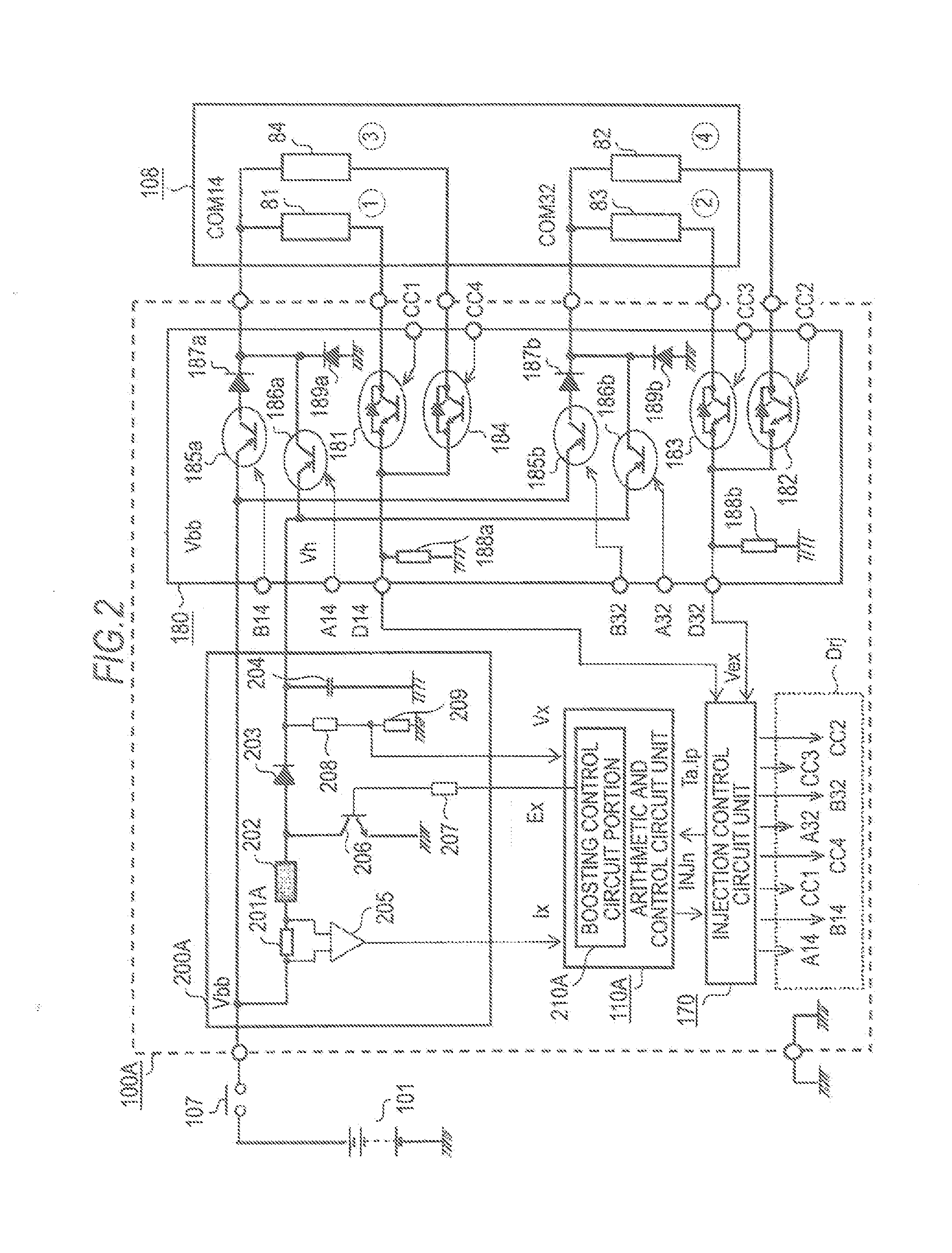
[0069]As is clear from the above description, an in-vehicle engine control device according to Embodiment 1 of this invention is an in-vehicle engine control device 100A including an solenoid valve driving control circuit unit 180 for a plurality of electromagnetic coils 81 to 84 for driving solenoid valves in order to sequentially drive the solenoid valves 108 for fuel injection provided in respective cylinders of a multi-cylinder engine; a boosting circuit unit 200A which generates a boosted high voltage Vh for performing rapid excitation on the electromagnetic coils 81 to 84; an arithmetic and control circuit unit 110A which has a microprocessor 111 as a main constituent element; and an injection control circuit unit 170 which performs relay between the microprocessor 111 and the solenoid valve driving control circuit unit 180. The arithmetic and control circuit unit 110A includes a multi-channel A / D converter 114a operated at low speed...

embodiment 2

(3) Main Points and Features of Embodiment 2

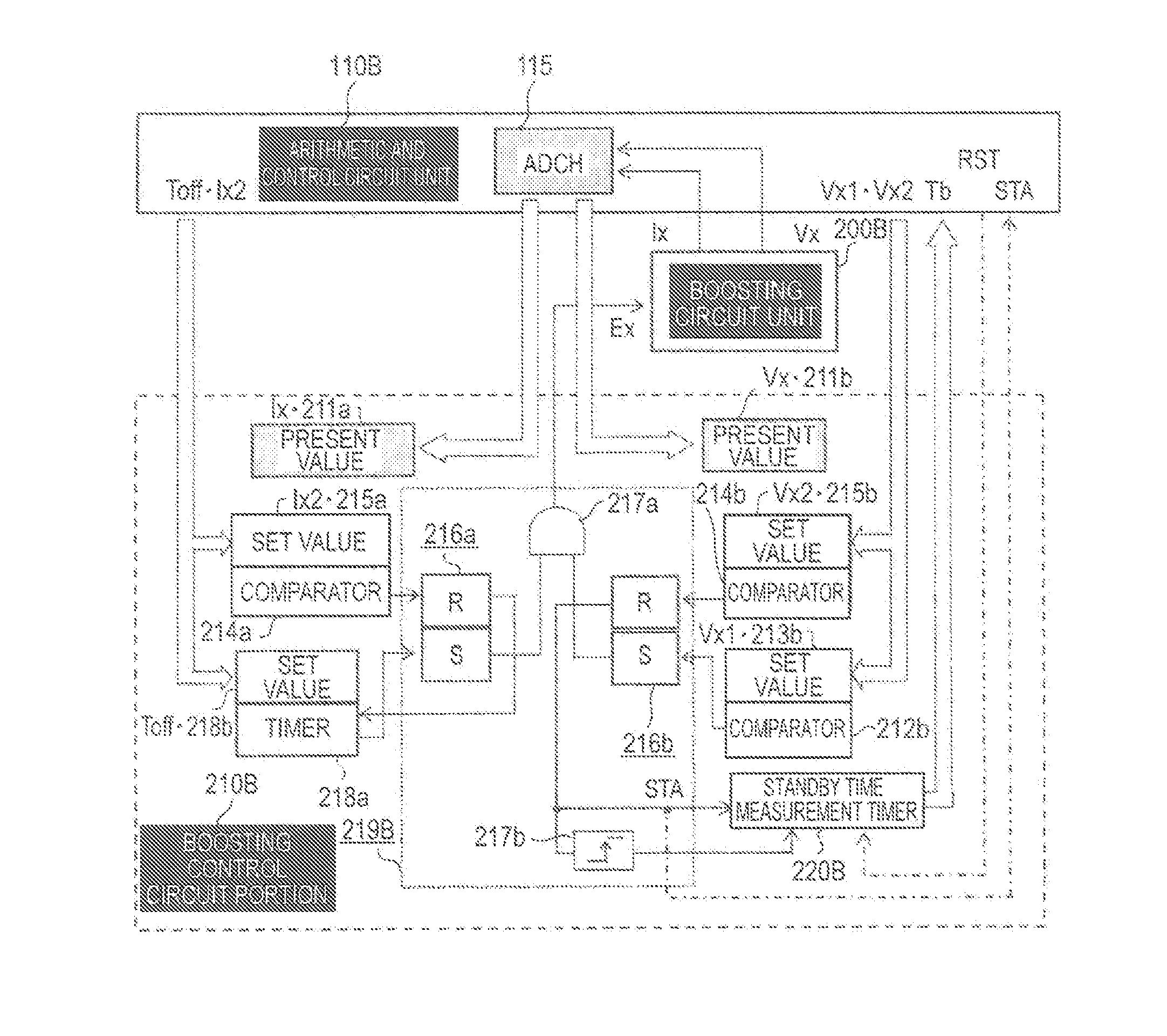
[0093]As is clear from the above description, an in-vehicle engine control device according to Embodiment 2 of this invention is an in-vehicle engine control device 100B including an solenoid valve driving control circuit unit 180 for a plurality of electromagnetic coils 81 to 84 for driving solenoid valves; a boosting circuit unit 200B which generates the boosted high voltage Vh for performing rapid excitation on the electromagnetic coils 81 to 84; an arithmetic and control circuit unit 110B which has a microprocessor 111 as a main constituent element; and an injection control circuit unit 170 performs relay between the microprocessor 111 and the solenoid valve driving control circuit unit 180, in order to sequentially drive fuel injection solenoid valves 108 provided in respective cylinders of a multi-cylinder engine. The arithmetic and control circuit unit 110B includes a multi-channel A / D converter 114a operated at low speed, which coo...

embodiments 1 and 2

Main Points and Features of Embodiments 1 and 2

[0105]As is clear from the above description, in an in-vehicle engine control method used for the in-vehicle engine control device according to Embodiment 1 or 2, the boosting control circuit portion 210A or 210B further includes a boosting period measurement timer 220A which measures a charging necessary time Tc after the valve opening command signals INJn (where n is 81 to 84) are generated until a charged voltage of the high-voltage capacitor 204 is reduced to the minimum voltage Vx0 due to rapid excitation for the electromagnetic coils 81 to 84 and arrives at the target higher-side voltage Vx2 through recharging, or a standby time measurement timer 220B which measures a charging allowance time Tb after the charged voltage arrives at the target higher-side voltage Vx2 until the next valve opening command signals INJn are generated. The program memory 113A or 113B cooperating with the microprocessor 111 includes a control program whic...


PUM


Abstract

In an inductive element which is intermittently excited by a boosting opening and closing element and charges a high-voltage capacitor to a high voltage, an inductive element current proportional to a voltage across both ends of a current detection resistor and a boosted detection voltage which is a divided voltage of the high-voltage capacitor are input to a boosting control circuit portion via a high-speed A / D converter provided in an arithmetic and control circuit unit. The boosting control circuit portion adjusts the inductive element current so as to be suitable for the time from the present rapid excitation to the next rapid excitation, and controls opening and closing of the boosting opening and closing element so as to obtain a targeted boosted high voltage which is variably set by a microprocessor of an arithmetic and control circuit unit.

Description

BACKGROUND OF THE INVENTION[0001]1. Field of the Invention[0002]This invention relates to an in-vehicle engine control device which rapidly excites an electromagnetic coil for driving a solenoid valve by using a boosting circuit unit which generates a high voltage from an in-vehicle battery and then performs valve-opening holding control by using a voltage of the in-vehicle battery, in order to drive the solenoid valve for fuel injection of an internal combustion engine at high speed, and particularly to an in-vehicle engine control device including an improved boosting circuit unit for obtaining a boosted high voltage and a control method thereof.[0003]2. Description of the Background Art[0004]There is an in-vehicle engine control device which sequentially generates valve opening command signals to a plurality of electromagnetic coils which are respectively provided for cylinders of a multi-cylinder engine and drive a fuel injection solenoid valve by using a microprocessor which is...

Claims


Application Information

Patent Timeline
Patent Type & Authority Applications(United States)
IPC IPC(8): F02D41/28F02D41/20
CPCF02D41/20F02D41/28F02D2041/2003F02D2041/2051F02D2041/2058F02D2041/2006F02D2041/201F02D2041/2013
Inventor NISHIDA, MITSUNORINISHIZAWA, OSAMU
Owner MITSUBISHI ELECTRIC CORP
Why Eureka
Try Eureka