
Micromachined oxygen sensor and method of making the same

a micro-machined oxygen sensor and oxygen sensor technology, applied in the field of micro-machined oxygen sensors or micro-electromagnetic systems, can solve the problems of long response time and limited life time, high cost, and high cost, and achieve the effects of low cost, fast response time and easy manufacturing

Active Publication Date: 2014-10-30
WISENSTECH
View PDF3 Cites 14 Cited by
  • Summary
  • Abstract
  • Description
  • Claims
  • Application Information

AI Technical Summary

Benefits of technology

This patent describes the design and manufacture of an oxygen concentration sensor that can measure the full scale of oxygen concentration and has a fast response time. It can operate at a lower temperature with a low power supply compared to existing ceramic oxygen sensors. It is robust and immune to environmental changes. It can be manufactured at a low cost and is suitable for general purpose oxygen measurements. The manufacturing process utilizes the MEMS manufacture process that is similar to the manufacture of integrated circuitry, which enables higher volume yields and lower costs per unit sensor product. The sensor utilizes an amperometric measurement principle that allows for larger dynamic ranges of oxygen concentration measurement. The design utilizes an electrolyte cell that pumps oxygen from one electrode to another, resulting in a much larger dynamic measurement range and making the final product easy for manufacture.

Problems solved by technology

However, most of the current oxygen sensors are manufactured with ceramic solid electrolyte or electrochemical cells that suffer a long response time and limited life time.
High accuracy oxygen concentration measurement can be achieved using paramagnetic oxygen sensing technology but it is extremely sensitive to vibration and bulk in size in addition to its high cost.
For many of the medical applications, response time is critical but the current technologies are yet to offer a practical solution.
However, the ceramic based sensor is not only limited to application of low oxygen concentration measurement but also costly for other applications such as motorcycle emission control.
The high temperature requirements of the ceramic oxygen sensors is however a drawback for ambient temperature applications as the local high temperature at the sensor is not desired and power requirement is large.
The high temperature requirements also limit the capability of sensor portability as the power shall not be sustainable with most of the available portable energy sources.
This structure is however in tact would be fragile as the limitation for the maximum silicon nitride thickness would be less than 1500 nm and the platinum interlace with silicon and silicon nitride thin film could suffer instability at the elevated temperature that is required for the oxygen sensing reaction for the zirconia oxide.
It further reported (Cole, B. E., Uk, E., Schuldt, S., and Bonne, U., Oxygen microsensor development, GRI Tech Report 86 / 0190, 1986) that such a structure would produce high compressive stress making the sensor unpractical for manufacture.
Nonetheless, it did not establish a conventional approach for the control of the temperature gradient and thus making the feasibility of practical manufacture of such is unclear.
Further the above disclosed oxygen sensors are most suitable for combustion and emission control applications but not for an oxygen sensor with wide dynamic range and last response time that could be applied for general purpose oxygen concentration measurement.
The other oxygen sensors using paramagnetic principle are too costly for the said applications and are best for laboratory use with extremely sensitive to vibration and environmental instabilities.

Method used


Image

  • Micromachined oxygen sensor and method of making the same
  • Micromachined oxygen sensor and method of making the same
  • Micromachined oxygen sensor and method of making the same

Examples


Embodiment Construction

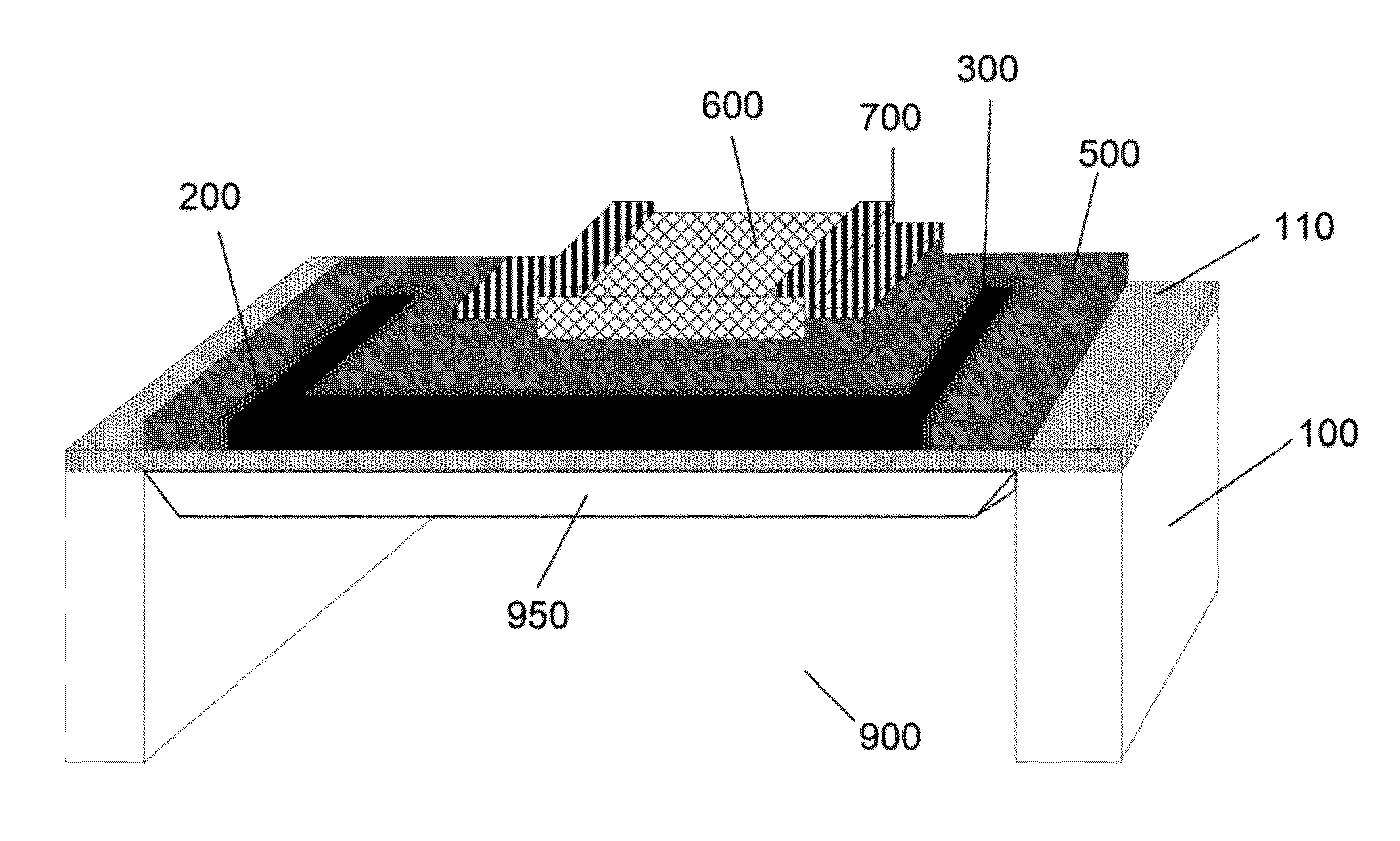
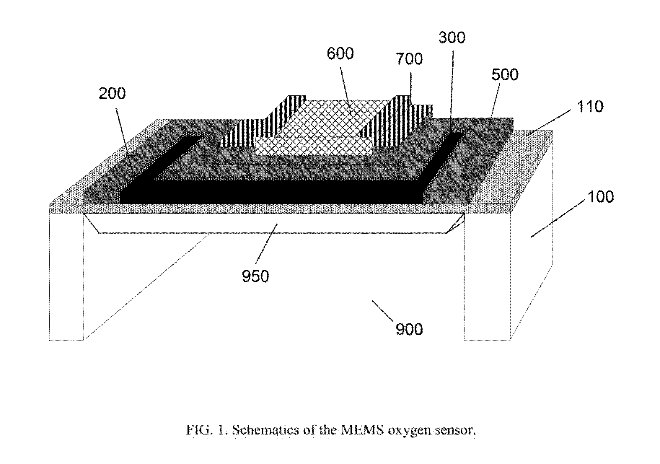
[0031]The preferred structure of the said micromachined oxygen concentration sensor is illustrated in FIG. 1. The substrate of toe sensor is preferably a silicon single crystal water 100, and the membrane 110 that supports the sensing hierarchy structure. The micro-heater 200 and the temperature sensor 300 shall form a microsystem that provides the required thermal energy for the sensing materials of the solid electrolyte. The sensing materials 600 is preferably yttrium stabilized zirconia oxide and the two electrodes 700 with porous platinum form the amperometric cells for the oxygen concentration sensing at a large dynamic range.

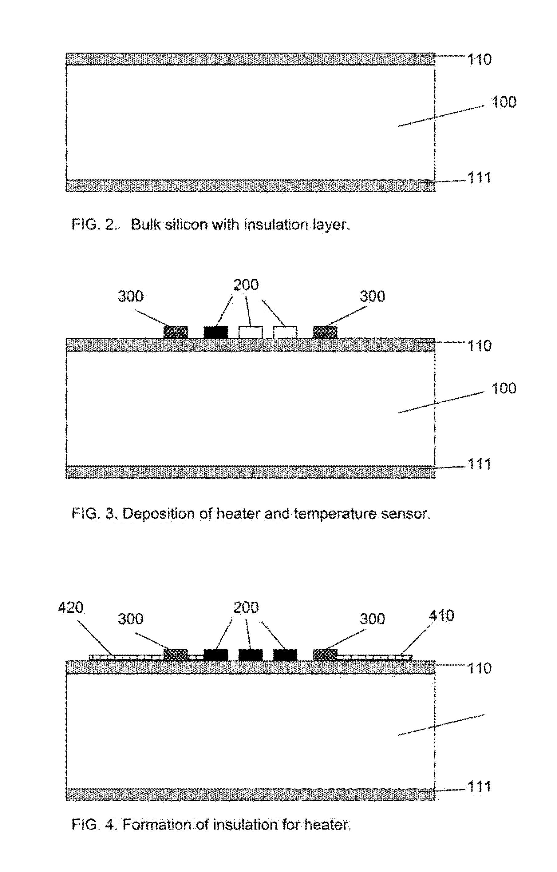
[0032]The preferred mieromachining process for making of the said invention starts from the preparation of the isolation cavity process mask and process stop (110 and 111) on the single crystal silicon substrate (100) with a thickness from 0.35 to 0.50 mm. Then the process is followed by the membrane formation for supporting the sensing hierarchy structure...


PUM

PropertyMeasurementUnit
operating temperatureaaaaaaaaaa
sizeaaaaaaaaaa
temperatureaaaaaaaaaa

Abstract

The design and manufacture method of an oxygen concentration sensor made with silicon micromachining (a.k.a. MEMS, Micro Electro Mechanical Systems) process for applications of oxygen measurement with fast response time and low power consumption is disclosed in the present invention. The said silicon oxygen concentration sensor operates with an yttrium stabilized zirconia oxide amperometric cell supported on a membrane made of silicon nitride with a heat isolation cavity underneath or a silicon nitride membrane with silicon plug for mechanical strength enforcement.

Description

BACKGROUND OF IMF INVENTION[0001]1. Field of the Invention[0002]This invention relates to micromachined silicon sensors or Micro Electro Mechanical Systems (MEMS) gas sensing technology that measures the quality of gases. The present invention also relates to gas concentration sensors of such gases. This invention additionally provides the design and make of a micromachined gas concentration sensor. The present invention specifically relates design and process of making the same for an oxygen concentration sensor using semiconductor solid electrolyte for applications in medical oxygen delivery, automotive fuel efficiency and other industrial emission control equipment.[0003]2. Description of the Related Art[0004]Oxygen concentration sensors have been widely used in gaseous environment such as analytical instrumentation, medical, equipment, automotive exhaust electronic contral unit (ECU), industrial emission control and environment control. However, most of the current oxygen sensor...

Claims


Application Information

Patent Timeline
Patent Type & Authority Applications(United States)
IPC IPC(8): G01N27/407
CPCG01N27/4073G01N27/4071G01N27/409
Inventor HUANG, LIJICHEN, CHIH-CHANG
Owner WISENSTECH
Learn More