Memory element, memory apparatus

a memory element and memory technology, applied in the field of memory element and memory apparatus, can solve the problems of increasing capacity and lowering power consumption, and achieve the effect of achieving a sufficiently large operation margin of the memory element, avoiding operation errors, and well-balanced properties

Active Publication Date: 2014-10-30
SONY CORP
View PDF8 Cites 19 Cited by
  • Summary
  • Abstract
  • Description
  • Claims
  • Application Information

AI Technical Summary

Benefits of technology

[0029]According to the present disclosure, because a memory element having a high perpendicular magnetic anisotropy is obtained, it is possible to configure a memory element having well-balanced properties while ensuring the thermal stability serving as an information holding capacity sufficiently.
[0030]Accordingly, it is possible to eliminate the operation error and to obtain an operation margin of the memory element sufficiently. Therefore, it is possible to realize a memory that stably operates with a high reliability.
[0031]Moreover, it is possible to decrease the writing current, and to decrease the power consumption when writing is performed on the memory element.
[0032]Therefore, it is possible to decrease the power consumption of the entire memory apparatus.

Problems solved by technology

However, it has challenges related to lowering power consumption and increasing capacity actually.
This is a basic problem caused by the recording principle of the MRAM, that is, the method of inverting the magnetization using a current magnetic field generated from an interconnection.

Method used


Image

  • Memory element, memory apparatus
  • Memory element, memory apparatus
  • Memory element, memory apparatus

Examples


experiment regarding embodiment

4. Experiment Regarding Embodiment

[0161]Here, in regard to the configuration of the memory elements 3 and 20 of this embodiment shown in FIG. 3A and FIG. 3B, experiments in which samples were prepared and then characteristics thereof were examined were conducted.

[0162]The conducted experiments are an experiment 1 and an experiment 2. The experiment 1 was conducted to obtain the temperature change of perpendicular anisotropy. The experiment 2 was conducted to calculate the value of thermal stability index by the measurement of a magnetic resistance curve and to measure the value of an inversion current.

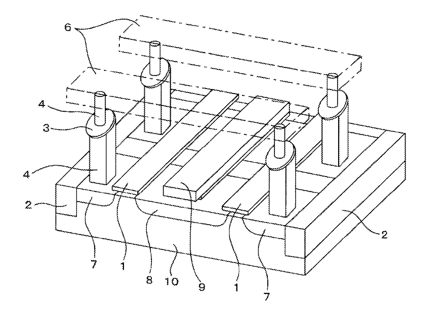
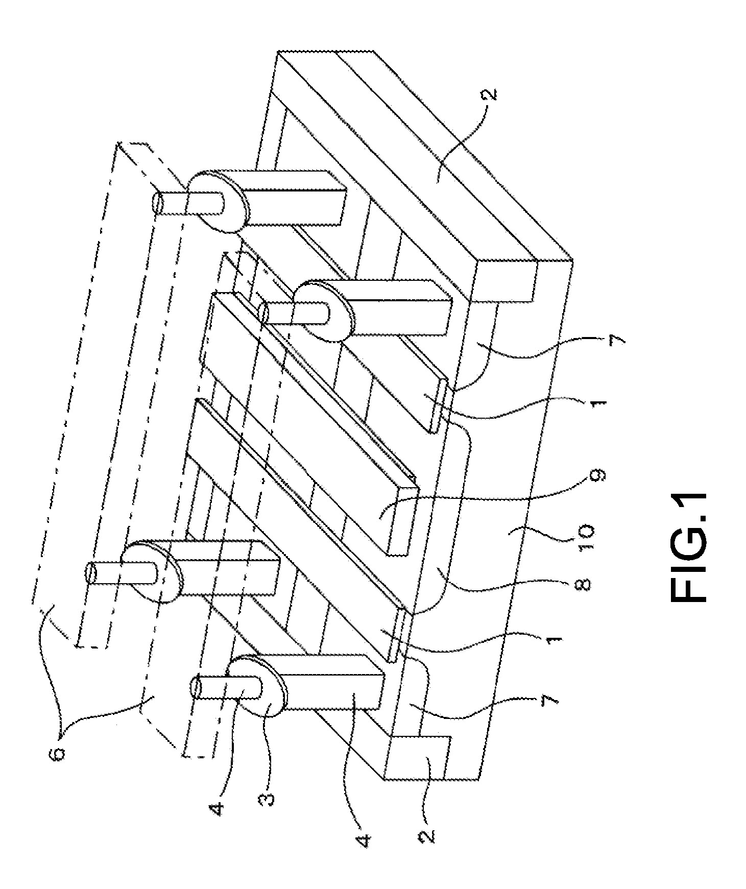
[0163]In an actual memory apparatus, as shown in FIG. 1, a semiconductor circuit for switching or the like is present in addition to the memory elements 3 and 20, but here, the examination was conducted on a wafer in which only a memory element is formed in order to check the magnetization inversion properties of the memory layer 17 adjacent to the cap layer 18.

[0164]As the sample of a...

experiment 1

[0179]This experiment was conducted to obtain the temperature change of perpendicular anisotropy of each sample described above.

[0180]The magnetization curve of the memory element is measured by magnetic kerr effect measurement and a Vibrating Sample Magnetometer to obtain the temperature change of the perpendicular anisotropy. For the measurement, not the element after being subject to minute processing but a bulk film portion having a size of about 8 mm×8 mm, which was specially provided on a wafer for magnetization curve evaluation, was used. Moreover, the measurement magnetic field was applied in the direction perpendicular to a film face.

[0181]FIG. 5 shows the obtained change of the perpendicular magnetic anisotropy of the samples 1 to 5 with respect to environment temperature. The temperature change of the magnetic anisotropy of the sample 2 and the samples 3 to 5 is larger than that of the sample 1. However, even in this case, there is no problem because the perpendicular mag...

experiment 2

[0191]In this experiment, in order to evaluate the writing properties of the memory element, the calculation of the value of the thermal stability index by the measurement of the magnetoresistance curve and the measurement of the inversion current value are performed in each sample described above.

[0192]A current with a pulse width of 10 μs to 100 ms was applied to the memory element, and the subsequent resistance value of the memory element was measured. Furthermore, the amount of currents applied to the memory element was changed, and the current value at which the direction of the magnetization of the memory layer of the memory element is inverted was obtained.

[0193]Moreover, the distribution of the coercive force obtained by measuring the magnetoresistance curve of the memory element a plurality of times corresponds to the index (Δ) of the holding properties (thermal stability) of the memory element. As the measured distribution of the coercive force is less, a higher Δ value is...


PUM


Abstract

[Object] To provide a memory element having well-balanced properties while ensuring the thermal stability.[Solving Means] A memory element includes a layered structure including a memory layer having magnetization perpendicular to a film face in which a direction of the magnetization is changed depending on information, a magnetization-fixed layer having magnetization perpendicular to the film face, which becomes a base of the information stored in the memory layer, and an intermediate layer that is formed of a non-magnetic material and is provided between the memory layer and the magnetization-fixed layer.Then, the memory layer includes a multilayer structure layer in which a non-magnetic material and an oxide are laminated, the direction of the magnetization of the memory layer being changed by applying a current in a lamination direction of the layered structure to record the information in the memory layer.

Description

TECHNICAL FIELD[0001]The present disclosure relates to a memory element and a memory apparatus that have a plurality of magnetic layers and make a record using a spin torque magnetization inversion.BACKGROUND ART[0002]Along with a rapid development of various information apparatuses from mobile terminals to large capacity servers, further high performance improvements such as higher integration, increases in speed, and lower power consumption have been pursued in elements such as a memory and a logic configuring this. In particular, a semiconductor non-volatile memory has significantly progressed, and, as a large capacity file memory, a flash memory is spreading at such a rate that hard disk drives are replaced with the flash memory. Meanwhile, the development of FeRAM (Ferroelectric Random Access Memory), MRAM (Magnetic Random Access Memory), PCRAM (Phase-Change Random Access Memory), or the like has progressed as a substitute for the current NOR flash memory, DRAM or the like in g...

Claims


Application Information

Patent Timeline
Patent Type & Authority Applications(United States)
IPC IPC(8): H01L43/02H01L43/10
CPCH01L43/10H01L43/02G01R33/093G11B5/3909G11C11/16H10B61/22H10N50/85H10N50/10G11C11/161H10B61/00H10B61/10H10B61/20H10B63/84H10N50/80H01L29/82
Inventor UCHIDA, HIROYUKIHOSOMI, MASANORIOHMORI, HIROYUKIBESSHO, KAZUHIROHIGO, YUTAKAASAYAMA, TETSUYAYAMANE, KAZUTAKA
Owner SONY CORP
Why Eureka
Try Eureka