Film mirror, film mirror manufacturing method, film mirror for photovoltaic power generation, and reflection device for photovoltaic power generator

a film mirror and photovoltaic power generation technology, applied in the field of film mirrors, can solve the problems of not being able to continue to use fossil fuels at the current rate, not being able to achieve the effect of sustaining the survival of mankind in the future, and efficiently concentrating solar light, excellent weather resistance and high reflectivity

Active Publication Date: 2014-11-20
KONICA MINOLTA INC
View PDF7 Cites 12 Cited by
  • Summary
  • Abstract
  • Description
  • Claims
  • Application Information

AI Technical Summary

Benefits of technology

[0033]According to the present invention, a film mirror having high reflectivity for efficiently concentrating solar light and having excellent weather resistance, a

Problems solved by technology

Global warming in recent years has developed into such a serious situation as to threaten even the survival of mankind in the future.
Accordingly, in the near future, it may be no longer possible to continue use of fossil fuels at the current rate.
Especially, since the vast desert spreads out near the equator called Sun Belt Places in the world, the solar energy poured thereto is quite inexhaustible supply.
However, even though solar energy is considered as a very strong alternative energy, in terms of utilizing it in social activities, it has problems such that (1) energy density of solar energy is low and (2) storage and transfer of solar energy are difficult.
However, although the glass mirror is highly durable for environments, it has disadvantages such as breakage during transport and significantly high weights, leading to high plant construction costs for providing necessary strength of mounts on which the

Method used


Image

  • Film mirror, film mirror manufacturing method, film mirror for photovoltaic power generation, and reflection device for photovoltaic power generator
  • Film mirror, film mirror manufacturing method, film mirror for photovoltaic power generation, and reflection device for photovoltaic power generator
  • Film mirror, film mirror manufacturing method, film mirror for photovoltaic power generation, and reflection device for photovoltaic power generator

Examples


example 1

Manufacture of Film Mirror of Example 1

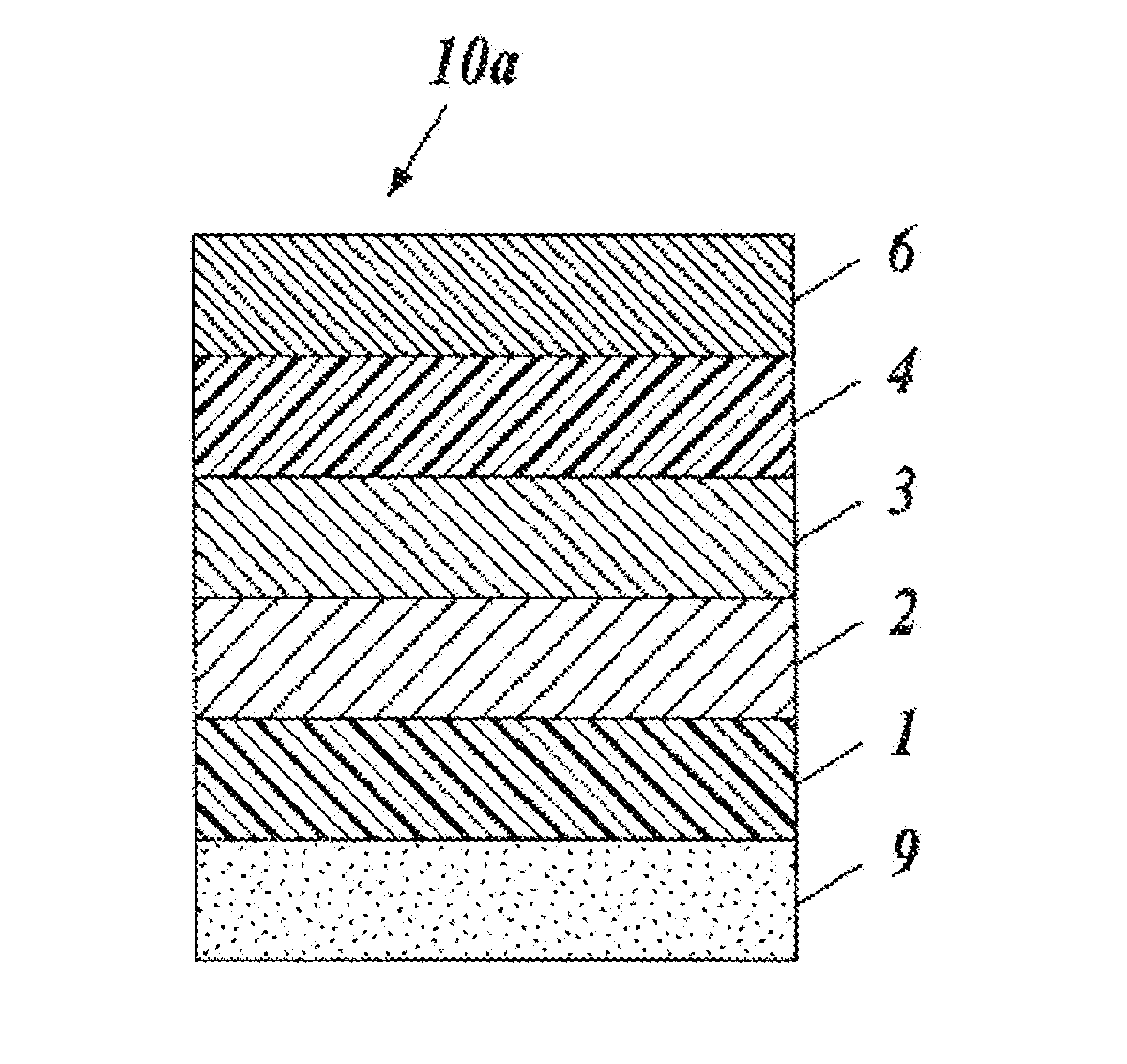
[0417]A biaxially-stretched polyester film (polyethylene terephthalate film having a thickness of 25 μm) was used as the resin substrate 1.

[0418]On one side of the above-mentioned polyethylene terephthalate film, a resin liquid in which polyester resin (POLYESTER SP-181 produced by Nippon Synthetic Chemical Industry Co., Ltd.), a melamine resin (Super Beckamine J-820 produced by DIC), TDI-based isocyanate (2,4-tolylene diisocyanate), and HMDI-based isocyanate (1,6-hexamethylene diisocyanate) are mixed in toluene such that the resin solid content ratio is 20:1:1:2 and the solid matter concentration is 10% was coated by a gravure coating method to form the anchor layer 2 with a thickness of 0.1 μm.

[0419]On the anchor layer 2, a silver reflective layer with a thickness of 100 nm was formed by a vacuum vapor deposition method.

[0420]Further, on the silver reflective layer, mixed resin of polyester resin and TDI-based isocyanate with a resin solid co...

example 2

Manufacture of Film Mirror of Example 2

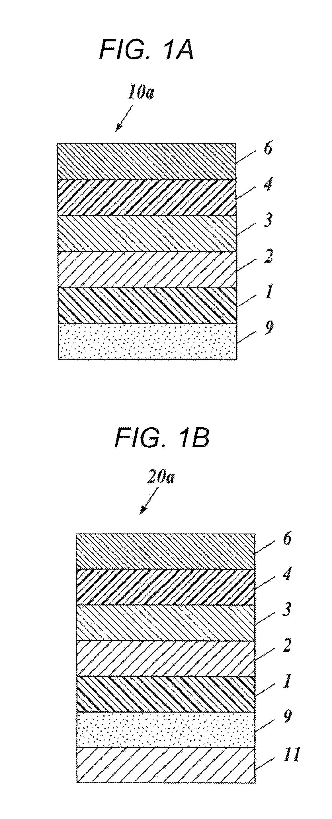
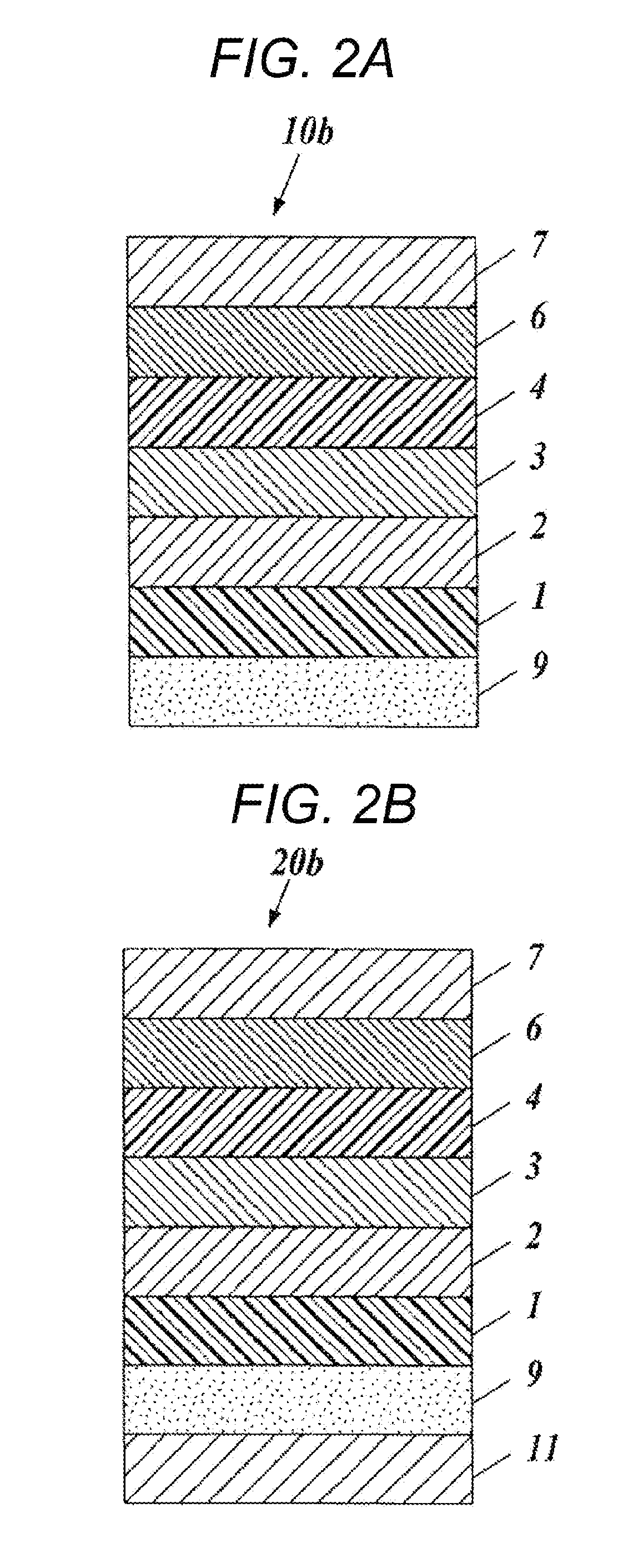
[0430]The film mirror 10b of Example 2 was obtained in the same method as Example 1 except that, on top of the outermost layer (on the dielectric reflective layer 6) of the film mirror 10a of Example 1, the ultraviolet absorbing layer 7 consisting of an acrylic resin material was additionally formed by coating to have a dry film thickness of 50 μm (see FIG. 2A).

[0431]To 800 ml MEK (methyl ethyl ketone), 150 g of the acrylic resin BR-85 and 50 g of BR-87 (all manufactured by Mitsubishi Rayon Co., Ltd.) were added in order under stirring and dissolved for 1 hour at 50° C. After confirming the dissolution of the acrylic resins, 1 g of TINUVIN1577 and 4 g of TINUVIN234 (all manufactured by BASF) were added as an UV absorbing agent. By dissolving for 30 minutes under stirring, a coating liquid for ultraviolet absorbing layer consisting of an acrylic resin material was produced.

[0432]Further, the reflection device for photovoltaic power generation 20...

example 3

Manufacture of Film Mirror of Example 3

[0433]The film mirror 10b of Example 3 was obtained in the same method as Example 2 except that the coating liquid “H3” for a high refractive index layer and the coating liquid “L3” for a low refractive index layer described below were used instead of the coating liquid “H2” for a high refractive index layer and the coating liquid “L2” for a low refractive index layer for the film mirror 10b obtained from Example 2 (see FIG. 2A).

[0434]The coating liquid “H3” for a high refractive index layer and the coating liquid “L3” for a low refractive index layer were prepared in the same manner as the coating liquid “H2” for a high refractive index layer and the coating liquid “L2” for a low refractive index layer except that polyvinyl alcohol (hereinbelow, also referred to PVA) (polyvinyl alcohol 235, manufactured by Kuraray Co., Ltd.) was used in the same amount as gelatin mass (gelatin with a low molecular weight+gelatin with high molecular weight) ins...


PUM

PropertyMeasurementUnit
Thicknessaaaaaaaaaa
Thicknessaaaaaaaaaa
Thicknessaaaaaaaaaa

Abstract

The purpose of the present invention is to provide a film mirror having a high reflectivity for efficiently concentrating solar light and having excellent weather resistance, and to provide a method for manufacturing the film mirror, a film mirror for photovoltaic power generation, and a reflection device for photovoltaic power generation. This film mirror of the present invention is a film mirror 10a in which a metal reflective layer 3 is disposed above a resin substrate 1. The film mirror is characterized in that it is provided with, closer to the light incident side than the metal reflective layer 3, an interface reflective layer (dielectric reflective layer) 6 having at least one set of a high refractive index layer and a low refractive index layer that are adjacent to each other, and at least one of the high refractive index layer and the low refractive index layer contains a water soluble polymer and metal oxide particles.

Description

CROSS REFERENCE TO RELATED APPLICATIONS[0001]This is the U.S. national stage of application No. PCT / JP2012 / 084151, filed on 18 Dec. 2012. Priority under 35 U.S.C. §119(a) and 35 U.S.C. §365(b) is claimed from Japanese Application No. 2012-001108, filed 6 Jan. 2012, the disclosure of which is also incorporated herein by reference.TECHNICAL FIELD[0002]The present invention relates to a film mirror, a manufacturing method thereof, a film mirror for photovoltaic power generation, and a reflection device for photovoltaic power generation.BACKGROUND ART[0003]Global warming in recent years has developed into such a serious situation as to threaten even the survival of mankind in the future. The main cause of global warming has been believed to be atmospheric carbon dioxide (CO2) emitted from fossil fuels which have been used in large amounts as energy sources in the 20th century. Accordingly, in the near future, it may be no longer possible to continue use of fossil fuels at the current ra...

Claims


Application Information

Patent Timeline
IPC IPC(8): G02B5/08B05D5/06G02B1/10G02B19/00F24S23/70
CPCG02B5/0866G02B19/0019G02B1/10G02B19/0042B05D5/063G02B19/009B32B15/08G02B1/14H01L31/056B32B27/306B32B2307/416B32B2307/418B32B2307/712B32B2457/12B32B2551/08Y02E10/40Y02E10/52F24S23/82F24S40/40
Inventor ADACHI, HITOSHI
Owner KONICA MINOLTA INC
Why Eureka
Try Eureka