Cladding mode stripper

a technology of optical fiber and mode stripper, which is applied in the direction of optical fibre with multi-layer core/cladding, optical waveguide light guide, instruments, etc., can solve the problems of degradation or catastrophic damage of fiber coating (acrylate/silicon), and achieve the effect of reducing operating temperatures and high efficiency

Inactive Publication Date: 2014-12-11
PRIMA ELECTRO NORTH AMERICA
View PDF6 Cites 39 Cited by
  • Summary
  • Abstract
  • Description
  • Claims
  • Application Information

AI Technical Summary

Benefits of technology

[0009]In this regard, the present invention provides for an improved arrangement for stripping stray light energy that is propagating in the cladding layer of an optical fiber. As such, the general purpose of the present invention, which will be described subsequently in greater detail, is to provide an improved cladding mode stripper that operates at a much higher efficiency as compared to the prior art in order to reduce operating temperatures at splices and complex optical devices downstream.
[0011]It is known that the greater the localized absorption of the cladding light the greater the localized heating of the fiber assembly. If the localized heating is too great, then there may occur gradual degradation or catastrophic damage to the fiber coating (acrylate / silicon / polyamide or other coating) and / or the epoxy / silicon / potting compound / coolant liquid / holder material that is near or in contact to the heat zone location. Accordingly, the present invention provides a cladding mode light stripping device, or series of devices that have purposeful design to distribute the light extraction and / or localized heating to allow removal of many watts (>100 W) of cladding light without device damage and / or with long device lifetime.
[0012]It is an object of the present invention to provide a cladding light stripper that incorporates removal of at least a portion of the coating material and / or splicing the fiber to a fiber of differing diameter and / or having a bend of constant or decreasing or varying radius to efficiently remove cladding light while distributing heat dissipation in a controlled design across the device with respect to a specific direction of input (cladding) light.
[0019]Still another embodiment provides for the use of low loss material of specific refractive index, e.g. Quartz glass or a secondary layer(s) of potting material of specific refractive index(s), to guide stripped cladding light away from the fiber to a physical location that light dissipation / absorption heating is thermally advantageous compared to the local vicinity of the fiber.

Problems solved by technology

If the localized heating is too great, then there may occur gradual degradation or catastrophic damage to the fiber coating (acrylate / silicon / polyamide or other coating) and / or the epoxy / silicon / potting compound / coolant liquid / holder material that is near or in contact to the heat zone location.

Method used


Image

  • Cladding mode stripper
  • Cladding mode stripper
  • Cladding mode stripper

Examples


Embodiment Construction

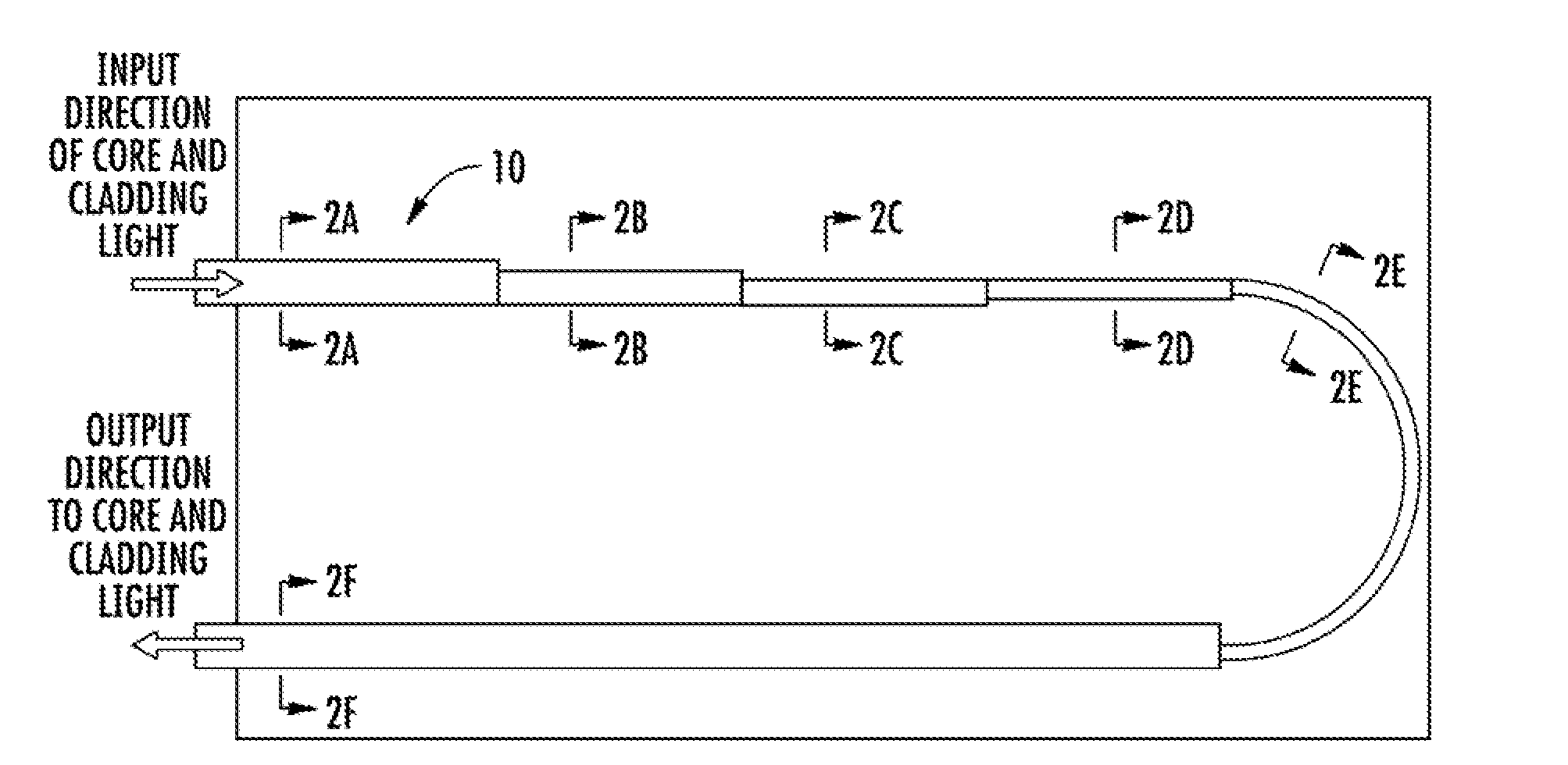
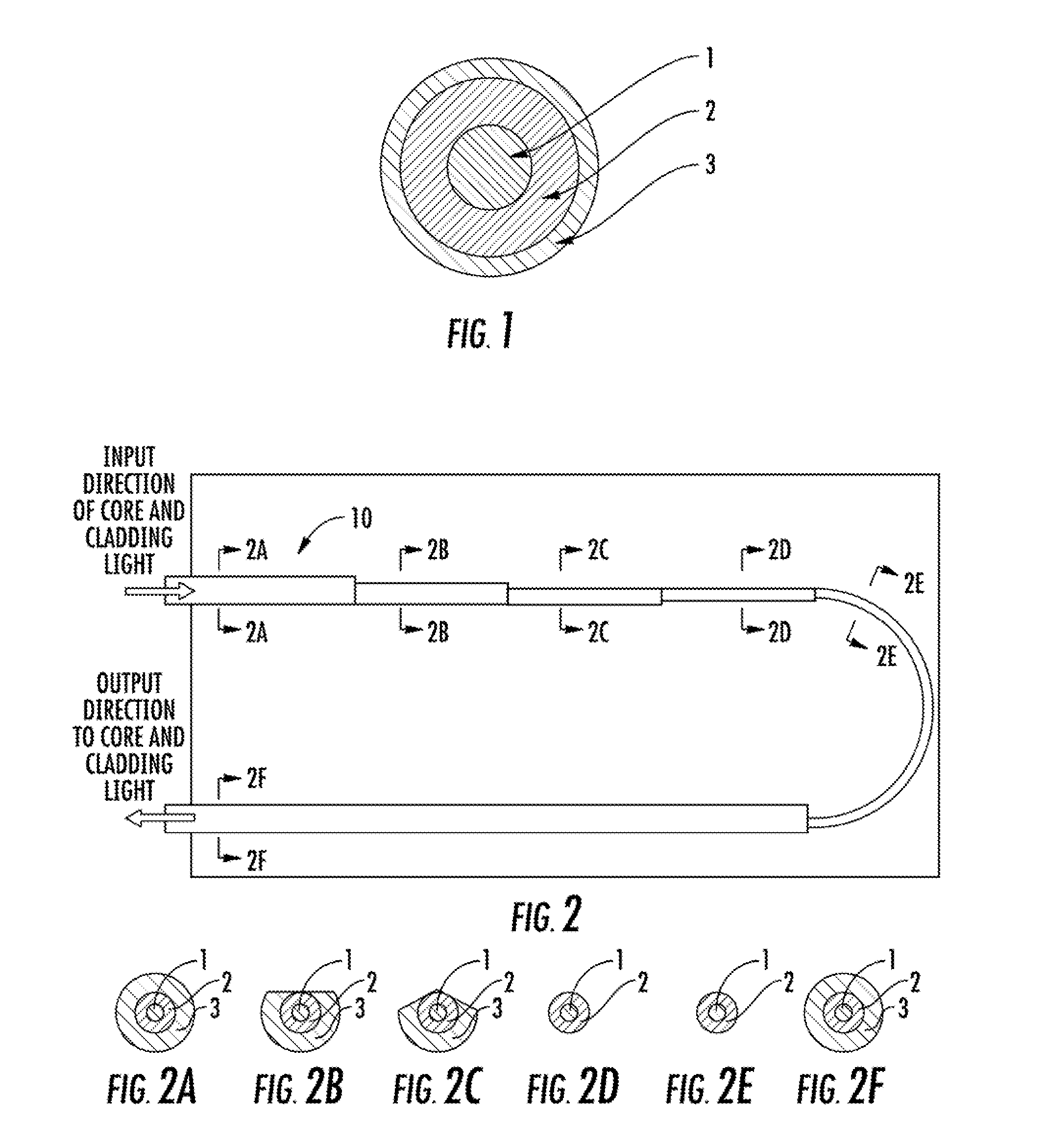
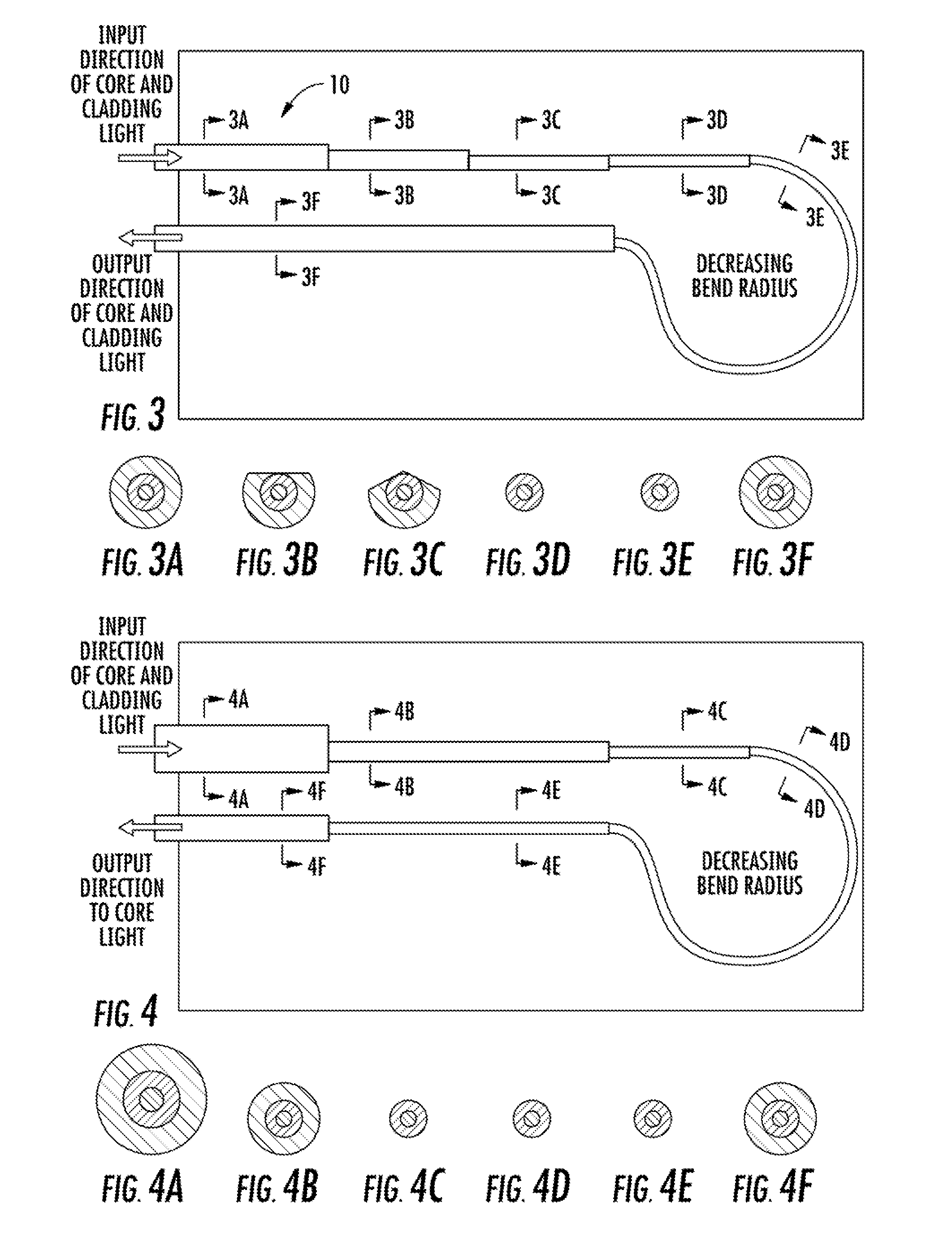
[0031]Now referring to the drawings, the system for removing cladding mode light from a fiber laser is shown and generally illustrated in the figures. As can be seen, the present invention provides an improved cladding mode stripper that operates at a much higher efficiency as compared to the prior art in order to reduce operating temperatures at splices and complex optical devices downstream.

[0032]As stated above, in high power fiber optic systems, such as may include fiber amplifiers, fiber lasers, and fiber coupled diode lasers, a significant amount of light may be guided in the cladding of the optical fiber for the purpose of excitation and amplification. However, a significant amount of the cladding light can remain in the cladding as the signal is passed into a transmission fiber so as to interfere with the output from the core. In certain circumstances, the cladding light can also be of a sufficient power level to heat the cladding, which can decrease performance and / or cause...


PUM


Abstract

An improved arrangement for stripping stray light energy that is propagating in the cladding layer of an optical fiber is provided. A cladding light stripper is provided that incorporates removal of at least a portion of the coating material and / or splicing the fiber to a fiber of differing diameter and / or having a bend of constant or decreasing or varying radius to efficiently remove cladding light while distributing heat dissipation in a controlled design across the device with respect to a specific direction of input (cladding) light.

Description

BACKGROUND OF THE INVENTION[0001]The present invention relates generally to stripping stray light energy from optical fiber assemblies. More specifically, the present invention relates to stripping stray light energy that is propagating in the cladding layer of an optical fiber.[0002]Advances in laser technology have allowed for the development of increasingly high powered systems. Such high powered systems include free space lasers, as well as lasers confined to waveguides, such as fiber lasers. Fiber lasers have significant advantages over traditional lasers, including stability of alignment, scalability and high optical power of a nearly diffraction limited output beam.[0003]In a fiber laser, the gain medium is a length of an optical fiber, the core of which is doped with an active lasing material, typically ions of a rare earth element, such as erbium or ytterbium or both. The lasing material is usually pumped using an emission of a diode laser or an array of diode lasers. The a...

Claims


Application Information

Patent Timeline
Patent Type & Authority Applications(United States)
IPC IPC(8): G02B6/036
CPCG02B6/036G02B6/14G02B6/2821G02B6/4291G02B6/4296
Inventor SCHWARZENBACH, PIETERSILVA SA, MATTHEW J.POZZI, FABIOREEVES-HALL, PETER
Owner PRIMA ELECTRO NORTH AMERICA
Why Eureka
Try Eureka