Process of forming a back side illumination image sensor
a back side illumination and image sensor technology, applied in the field of image sensors, can solve the problems of difficult to have a large margin on the second overlap, complicating process optimization, and inability to precisely control, so as to improve the overlap, reduce the surface dark current, and improve the accumulation of holes
- Summary
- Abstract
- Description
- Claims
- Application Information
AI Technical Summary
Benefits of technology
Problems solved by technology
Method used
Image
Examples
first embodiment
[0029]FIG. 3A to FIG. 3D show a sequence of cross sectional views that illustrates a process of forming a non-self aligned (non-SA) back side illumination (BSI) complementary metal oxide semiconductor (CMOS) image sensor (CIS) according to the present invention. It is noted that only layers or regions that are pertinent to the feature or features of the embodiment are discussed or shown. In other words, there may be further layer(s) or region(s) disposed between, on, below or adjacent to the shown layers or regions.
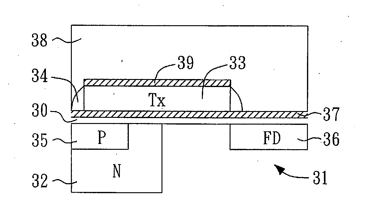
[0030]In FIG. 3A, all implants are within the top P type epitaxy portion of a semiconductor substrate 31 (e.g., a silicon substrate). A transfer gate (Tx) channel implant 30 such as p-type implant is formed in the semiconductor substrate 31. Subsequently, in FIG. 3B, an n-type doped region such as an n-type implant 32 is formed below the transfer gate channel implant 30. Next, in FIG. 3C, a thin gate oxide 37 is grown on the surface of substrate 31 and a transfer gate (Tx...
second embodiment
[0036]Moreover, the non-SA BSI CSI second embodiment can also benefit the burgeoning 3D CIS technology. It is shown in FIG. 6A a cross sectional view of the non-SA BSI CIS with extended transfer gate 33 at the pixel photo diode level along with circuit schematic of a portion of the pixel circuit (e.g., a reset transistor, a source follower SF and a select transistor SEL) at the pixel circuit level and two 3D vias 360 and 332 at FD 36 and Tx 33 respectively bridging the PD and Circuit levels in the vertical direction (the added 3rd dimension vs. the conventional 2D topology of Integrated Circuit). FIG. 6B shows a cross sectional view and circuit schematic of a counterpart without extended transfer gate. It is observed that the distance 330 between a transfer-gate 3D via 332 and a FD 3D via 360 may be substantially increased (compared to that shown in FIG. 6B), thereby reducing the coupling capacitance between them and thus increasing conversion gain.
[0037]The non-SA BSI CIS second em...
third embodiment
[0038]FIG. 8A to FIG. 8E show a sequence of cross sectional views that illustrates a process of forming a non-self aligned (non-SA) back side illumination (BSI) CMOS image sensor (CIS) according to the present invention.
[0039]In FIG. 8A, a semiconductor substrate 81 (for example, a silicon substrate) is provided. An n-type implant 82 is then formed in a top portion of the semiconductor substrate 81, followed by annealing (or heat treatment), therefore resulting in a structure shown in FIG. 8A. Subsequently, in FIG. 8B, a transfer gate channel implant 83, such as a p-type implant, is formed in a top portion of the n-type implant 82. Next, as shown in FIG. 8C, p-type implant region 84, that surrounds n-type implant 82, is formed in the n-type implant 82 such that as seen in cross section an n-type implant region 82A is sandwiched between the two p-type implant regions 84. Afterwards, in FIG. 8D, a transfer gate 85, such as a polysilicon gate, is formed on top of the transfer gate chan...
PUM
 Abstract
Description
Claims
Application Information
 - R&D
- Intellectual Property
- Life Sciences
- Materials
- Tech Scout
- Unparalleled Data Quality
- Higher Quality Content
- 60% Fewer Hallucinations
Browse by: Latest US Patents, China's latest patents, Technical Efficacy Thesaurus, Application Domain, Technology Topic, Popular Technical Reports.
© 2025 PatSnap. All rights reserved.Legal|Privacy policy|Modern Slavery Act Transparency Statement|Sitemap|About US| Contact US: help@patsnap.com


