Method for forming a solar cell with a selective emitter

Inactive Publication Date: 2015-01-15
REC SOLAR
View PDF3 Cites 12 Cited by
  • Summary
  • Abstract
  • Description
  • Claims
  • Application Information

AI Technical Summary

Benefits of technology

[0010]It is an object of the present invention to provide an alternative method of producing a solar cell with a selective emitter. Particularly, such method should b

Problems solved by technology

In homogeneously doped emitters a trade-off with respect to the doping concentration has to be made as e. g. low doping concentration may improve a spectral response of the solar cell

Method used


Image

  • Method for forming a solar cell with a selective emitter
  • Method for forming a solar cell with a selective emitter

Examples


Embodiment Construction

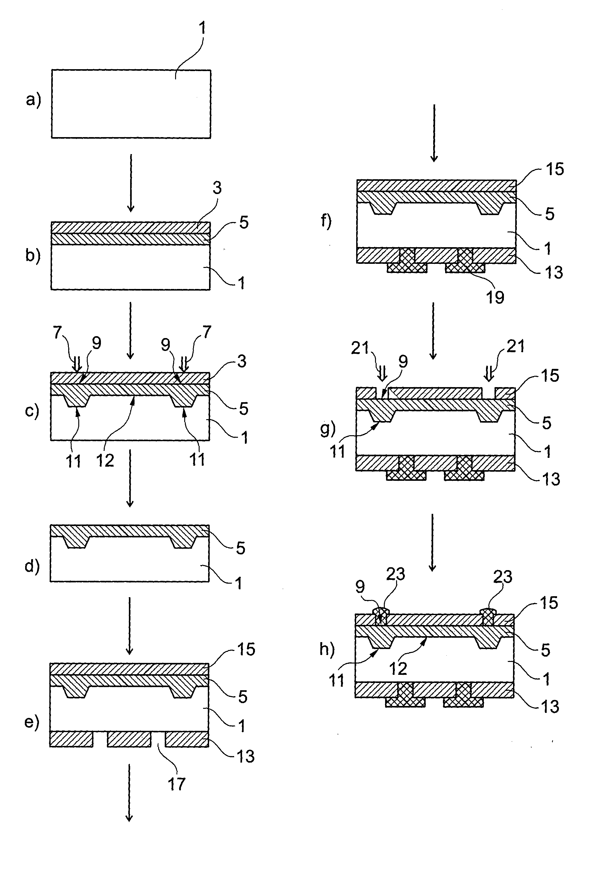
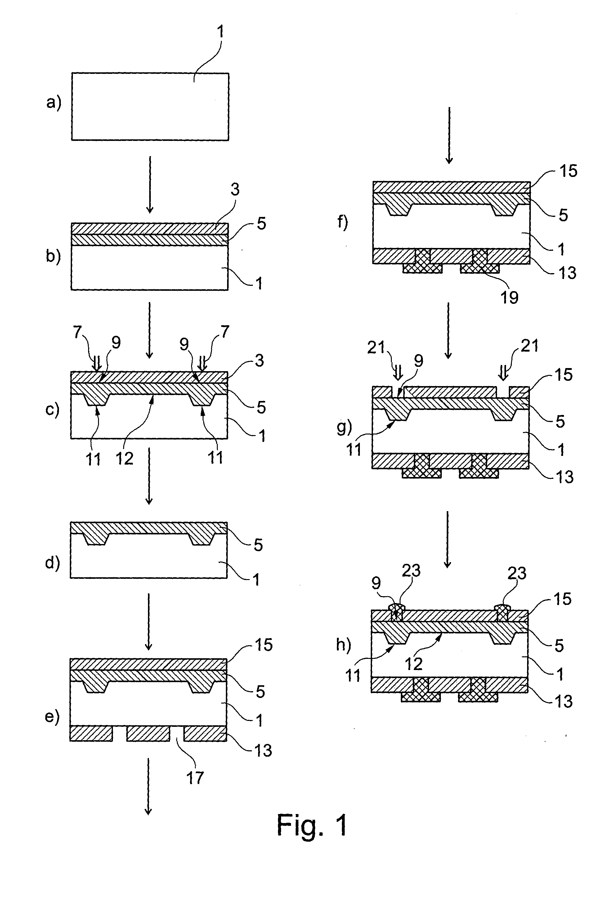
[0043]Referring to FIG. 1, a processing sequence for a method of producing a solar cell in accordance with an embodiment of the present invention is described.

[0044]In step (a), a semiconductor substrate 1 is provided as a silicon wafer having a homogeneous p-type base doping. The semiconductor substrate 1 may be pre-treated e.g. with saw-damage removal etch and / or polishing of its backside.

[0045]In step (b), a layer 3 of dopant source material is formed. In the specific example, this layer 3 is formed as a phosphorous silicate glass during a POCl3 diffusion step, in which the semiconductor substrate 1 is held in a POCl3 atmosphere at high temperatures of e. g. 800 to 900 degrees Celsius for a duration of e. g. 10 to 90 minutes.

[0046]Simultaneously with the formation of the layer 3 of dopant source material, dopants from such layer 3 diffuse into the front surface of the semiconductor substrate 1 due to the applied heat thereby forming a homogeneous lightly doped emitter region 5. T...


PUM


Abstract

A method for producing a solar cell with a selective emitter is disclosed. A semiconductor substrate (1) is provided. A layer (3) of dopant source material with a dopant type opposite to the dopant type of the substrate (1) is formed at a surface of the substrate (1). By applying heat to the layer (3), a homogeneous lightly doped emitter region (5) is formed. In a first lasering step, selective heavily doped emitter regions (11) are formed by applying laser light (7) to contact surface areas (9). Optionally, the layer (3) is subsequently removed and an additional dielectric layer (15) is applied to the front side of the substrate (1). In a second lasering step, the layer (3) or the layer (15) are locally removed by applying laser light (21) to the contact surface areas (9), thereby locally exposing the surface of the substrate (1). In the locally exposed contact surface areas (9), metal contacts (23) are finally formed, using for example metal-plating techniques. Using two different lasering steps for laser doping, on the one hand, and laser removal for forming the metallization mask, on the other hand, allows optimizing each of the lasering steps independently from each other, thereby enabling improvements for the processing and resulting solar cell.

Description

RELATED APPLICATIONS[0001]The present application claims the priority of the British patent application no. 1201881.8, filed on Feb. 2, 2012 as well as U.S. provisional patent application No. 61 / 594,155 filed on Feb. 2, 2012, whose content is incorporated into this document by reference.FIELD OF THE INVENTION[0002]The present invention relates to a method for forming a solar cell with a selective emitter.TECHNICAL BACKGROUND[0003]Solar cells are used to convert sunlight into electricity using a photovoltaic effect. A general object is to achieve high conversion efficiency and high reliability balanced by a need for low production costs.[0004]One approach of increasing the conversion efficiency of a solar cell is to provide the solar cell with what is known as a “selective emitter”.[0005]Generally, in a solar cell, a semiconductor substrate is provided with a doping of a base type and at a surface of such semiconductor substrate an emitter layer with an opposite doping is formed.[000...

Claims


Application Information

Patent Timeline
IPC IPC(8): H01L31/18H01L21/66
CPCH01L31/1864H01L22/12H01L31/022425Y02E10/547H01L31/02008H01L31/02021H01L31/0248H01L31/028H01L31/068H01L31/1804Y02E10/50
Inventor LAM, JENNYSTEEMAN, ROB
Owner REC SOLAR
Why Eureka
Try Eureka