Dielectric-Enhanced Metal Coatings for MEMS Tunable Filters

a metal coating and tunable filter technology, applied in the direction of optical radiation measurement, instruments, spectrometry/spectrophotometry/monochromators, etc., can solve the problems of reducing the high-speed performance of the tunable filter or other reflective structure of the fp tunable filter, and the tunable filter or other reflective structure is difficult to deflect or otherwise move. ,

Active Publication Date: 2015-02-12
EXCELITAS TECH
View PDF10 Cites 19 Cited by
  • Summary
  • Abstract
  • Description
  • Claims
  • Application Information

AI Technical Summary

Benefits of technology

[0013]In the design of optical resonators, it is often important to improve the reflectivity of the mirror structures. This is typically accomplished by increasing the number of thin dielectric film layers in the coatings of the mirror structures. This creates a problem in MOEMS FP tunable filters or other reflective structures, however. Increasing the number of layers increases the mass of the mirror structures. When these mirror structures

Problems solved by technology

This creates a problem in MOEMS FP tunable filters or other reflective structures, however.
When these mirror structures are then located on small moving elements, i.e. the optical membranes, these moving elements can become harder to deflect or otherwise move due to their increased mass, which can reduce their high-speed performance by reducing the mechanical resonant frequency of these moving el

Method used


Image

  • Dielectric-Enhanced Metal Coatings for MEMS Tunable Filters
  • Dielectric-Enhanced Metal Coatings for MEMS Tunable Filters
  • Dielectric-Enhanced Metal Coatings for MEMS Tunable Filters

Examples


Embodiment Construction

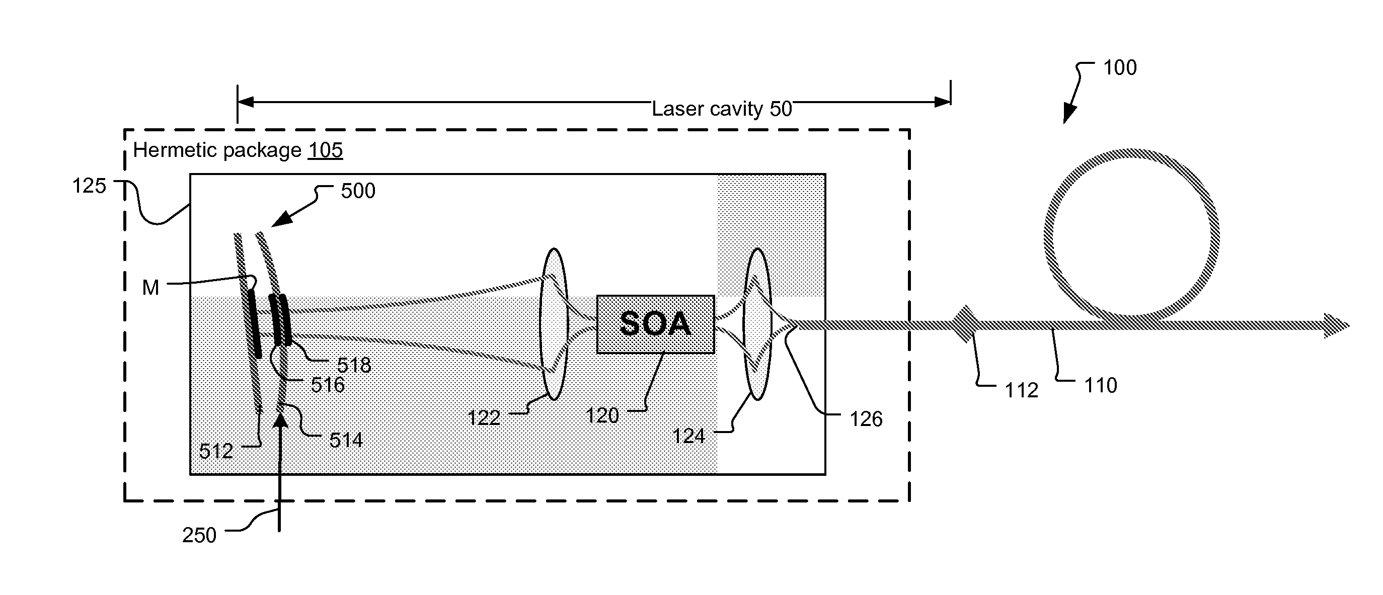
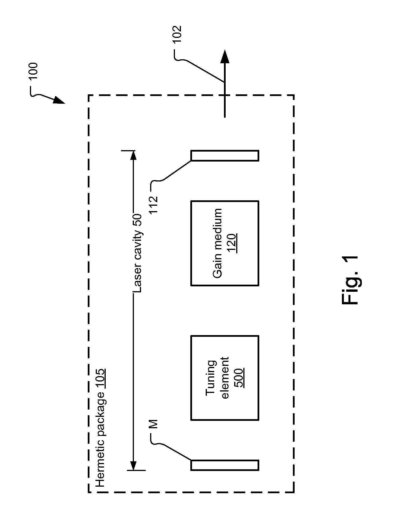
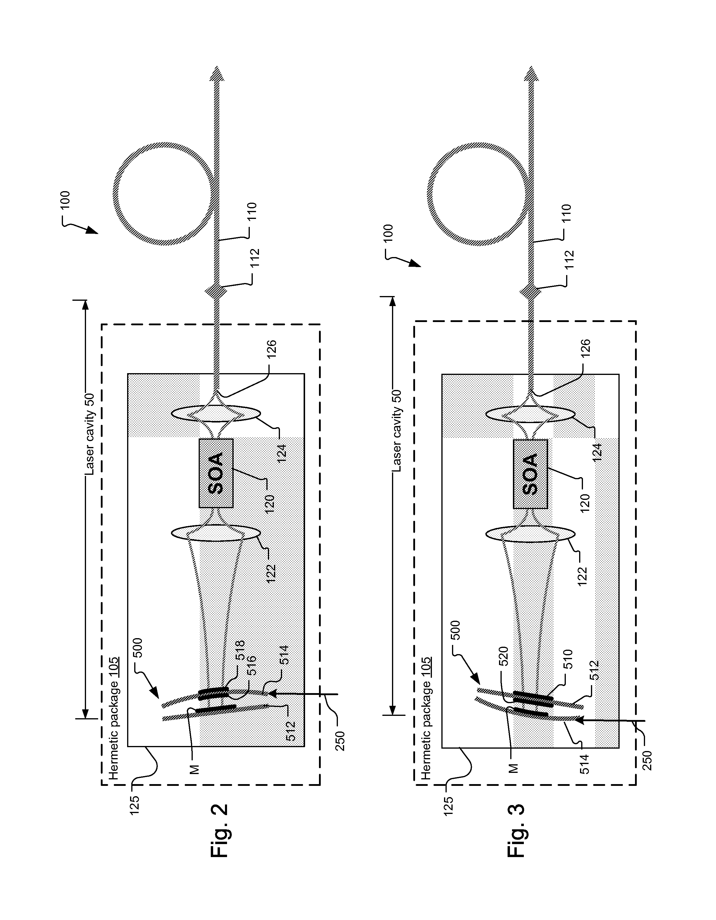
[0035]FIG. 1 illustrates a general tunable laser configuration and the use of hybrid metal-dielectric optical coatings in the laser, according to the principles of the present invention.

[0036]The hybrid metal-dielectric optical coatings generally have two advantages. First, they prevent stray light within a hermetic package 105, for example, since light that might be transmitted through a standard dielectric optical coating will be absorbed by the hybrid metal-dielectric optical coatings. Secondly, hybrid metal-dielectric optical coatings tend to have broader reflectivity spectrums, which is helpful in tunable lasers with broad spectral scan bands, since the reflectivity of the end mirror M will be more consistent, and high, over the scan band.

[0037]In more detail, the tunable laser 100 includes a tuning element 500 and a gain medium 120 within an optical cavity 50 defined by an output mirror 112 and a back mirror M. According to a typical application of the present invention, the b...


PUM


Abstract

The present invention concerns the use of hybrid metal-dielectric optical coatings as the end reflectors of laser cavities and/or in the mirror structures used in other optical resonators, such as Fabry-Perot tunable filters, along with the use of such Fabry-Perot tunable filters in wavelength swept sources such as lasers. Hybrid metal-dielectric optical coatings have reflectivity spectra that can be broader than pure dielectric coatings, offer optical reflectivities higher than metal, as high as pure dielectric coatings, eliminate mirror transmission that can cause parasitic light reflections, and use fewer layers and thus have lower mass and higher mechanical resonant frequency for movable mirror applications An important characteristic of these coatings concerns the non-reflected light. Pure dielectric coatings offer high reflectivity, while the non-reflected portion of the light is transmitted by the coating to the substrate, for example. When metal is added to the optical coating, the non-reflected portion of the light is absorbed by the metal and is not transmitted to the substrate or outside the cavity. Hybrid metal-dielectric coatings have broader and more uniform spectral reflection. Tunable lasers with performance enhanced by the hybrid metal-dielectric coatings can be used in optical coherence tomography and spectroscopic analysis applications.

Description

BACKGROUND OF THE INVENTION[0001]Optical resonators often include two or more mirror structures that define the resonator cavity. Optical resonators can be passive cavity devices as, for example, tunable Fabry-Perot (FP) filters. Active cavity devices also include a gain medium, such as a semiconductor or a solid-state material, inside the cavity between the mirror structures. A laser is an active cavity optical resonator.[0002]The earliest and simplest reflective optical mirror structures were made by applying a thin metal coating to a substrate. Typical metals for the coating are: gold (Au), silver (Ag), and aluminum (Al). Typical substrates include glass and silicon, for example. The advantage of metal mirrors is optical reflectivity over a very broad spectral range. The disadvantages are that the reflectivity is sometimes not high enough for high performance applications and the metal coatings are soft and can be damaged.[0003]For high performance cavities, requiring highly refl...

Claims


Application Information

Patent Timeline
IPC IPC(8): G02B5/28H01S5/06G01J3/28G01B9/02
CPCG02B5/28G01J3/28H01S5/06G01B9/02091G01J3/26H01S3/08059H01S3/105H01S5/0222H01S5/141H01S5/02251H01S5/02325G02B26/001
Inventor KUZNETSOV, MARK E.GALEB, RANKO
Owner EXCELITAS TECH
Why Eureka
Try Eureka