Precessional Drilling and Reaming

a technology of precessional drilling and reaming, which is applied in the direction of twist drills, wood boring tools, turning machine accessories, etc., can solve the problems of increasing friction and axial resistance, affecting the accuracy of drilling and/or workpieces, so as to achieve the effect of monotony reduction

Active Publication Date: 2015-02-26
SCIANAMBLO MICHAEL J
View PDF11 Cites 30 Cited by
  • Summary
  • Abstract
  • Description
  • Claims
  • Application Information

AI Technical Summary

Benefits of technology

[0030]Particular embodiments of the subject matter described in this document can be implemented to realize one or more of the following advantages. The cutting devices provided herein can create precision round, burr-less, and chip-free holes, without requiring the two-step process of drilling and reaming as with other techniques. The precessional cutting devices are also well-suited to drilling combinations of materials (e.g., stacked or hybridized materials). A precessional cutting instrument that is somewhat flexible and that has a center of mass offset from an axis of rotation may swing out from the axis of rotation as the instrument is rotated at high speeds. If the instrument is configured to bend an equal amount at each angle of rotation, the inner diameter of a space can be contacted by the instrument and uniformly machined. The instrument can be made to have a smaller diameter than the space that requires machining. Other advantages offered by the precessional drill designs include the intermittent contact of the lands and cutting edges of the drill with the material itself. In such a manner, the hole space can be enlarged more efficiently, and the material is kept cooler to avoid or reduce thermal expansion or deformation of the material. Intermittent contact can also facilitate irrigation, which can also improve the cutting efficiency of the instrument.

Problems solved by technology

A completely cylindrical twist drill encounters greater and greater friction and axial resistance as the device advances, which can cause premature wear and often damages the drill and / or work piece.
Although back taper 205 is useful and a standard feature is many drill designs, back taper 205 does not completely solve the aforementioned problems of friction and axial resistance.
An additional set of problems arise from “self-excited” or “regenerative” vibrations in hole making.
As the drill turns or cuts, a torsional load is placed on the cutting edges causing the drill to unwind or unravel.
This extension, however, is resisted by the downward thrust of the drill and by the drill's own torsional inertia or stiffness.
As the drill continues to rotate, it collides with these waves, and the waviness and oscillation both grow more severe.
The operator often describes this resonance as a pecking or jack-hammer effect, which creates premature tool wear, and can fracture the tool and / or damage the work piece and the machine components.
Increasing the penetration rate relative to the rpms may necessarily induce more rubbing and more friction, which may further stabilize the device.
While all of these suggestions may mitigate chatter to some extent, they may simultaneously serve to reduce the cutting efficiency of the drill and / or reamer and the cutting system itself.
Although the center of any one lobe may correspond to the drill size, the resultant lobulated space does not, making assembly using fasteners corresponding to the size of the drill less effective.
Again, while all of these suggestions may serve to mitigate low frequency vibrations, they may simultaneously serve to reduce the cutting efficiency of the drill and / or reamer and the cutting system itself.
Unfortunately, an increase in web thickness from 20% to 40% will require four times more axial force to operate the drill.
Unfortunately, drills with wide webs (between 20-40% of the diameter of the drill) have the highest rake angle and are the least efficient.
Attempts to thin the webs at the tip can only lead to premature drill wear and safety risks, and can create asymmetry in hole roundness.
However, most of the suggestions offered for mitigating machine tool vibrations have only come in the last few decades.
Other example uses include harder and / or more brittle materials such as glass or ceramics, which are challenging due to the material's poor edge strength and the substantial load that is required to create the perforation.
The rotating the cutting instrument includes may cause the cutting instrument to form sinusoidal waves within the space.

Method used


Image

  • Precessional Drilling and Reaming
  • Precessional Drilling and Reaming
  • Precessional Drilling and Reaming

Examples


Embodiment Construction

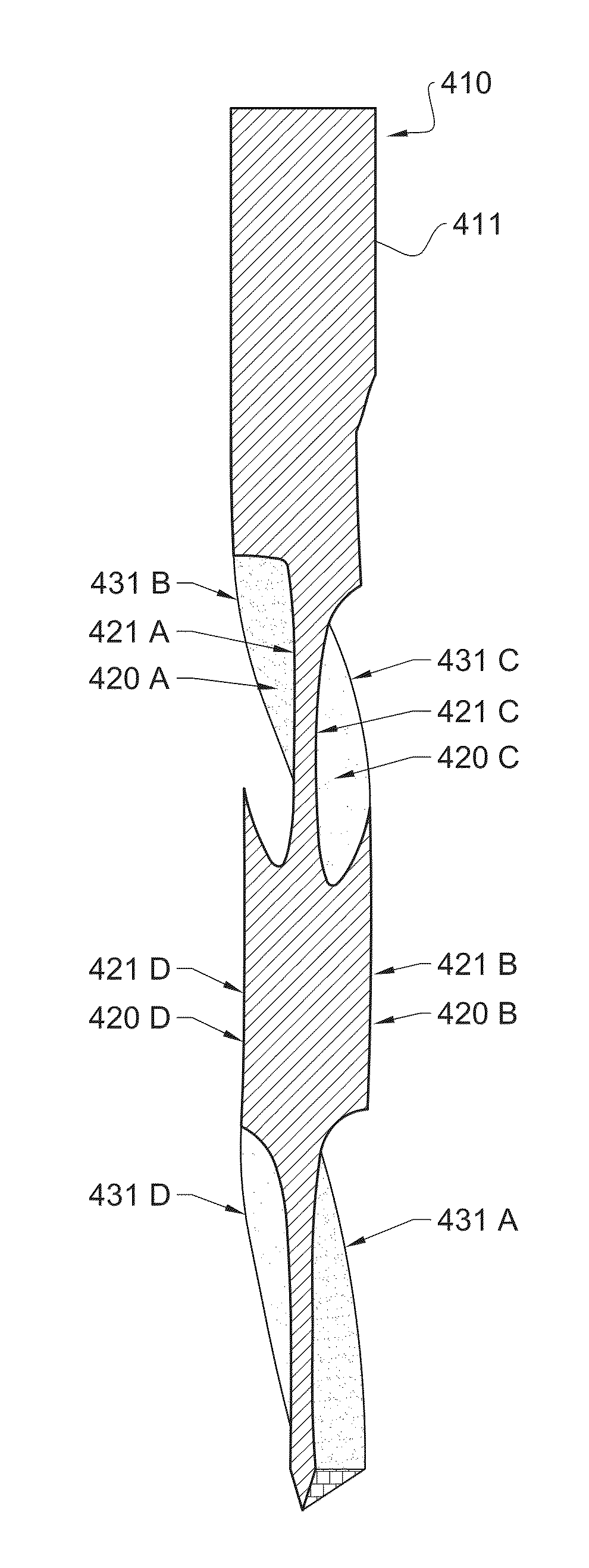
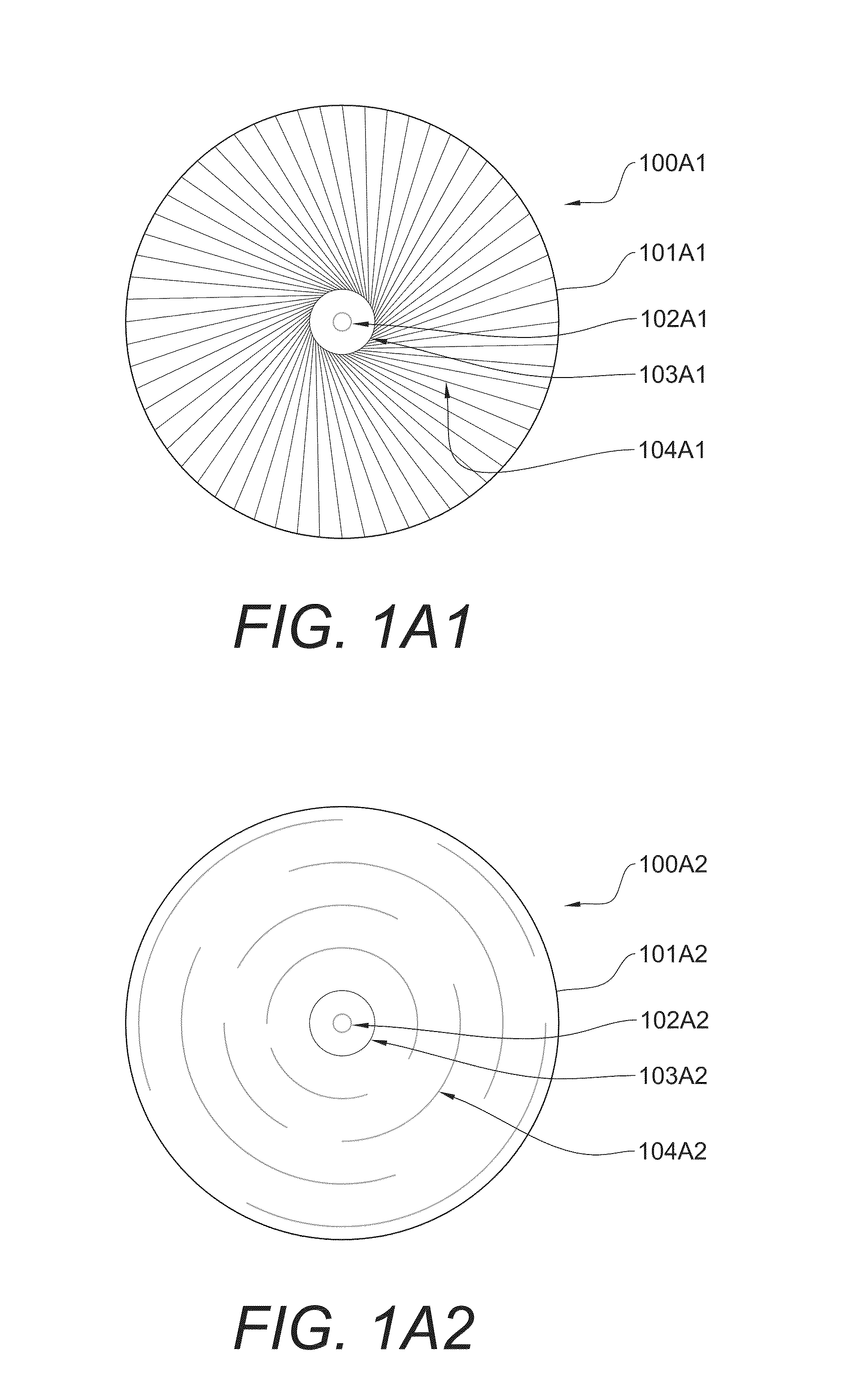
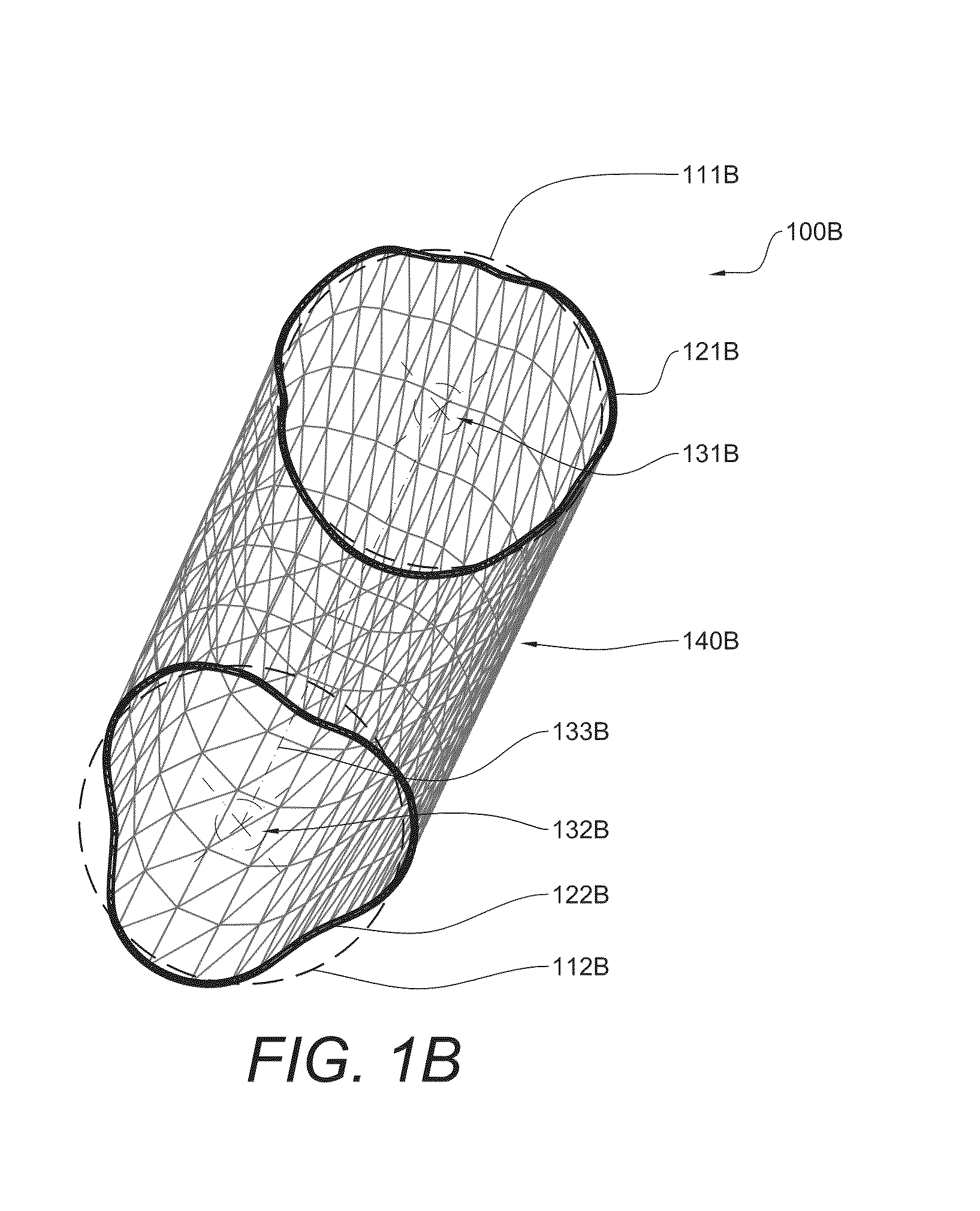
[0078]This document provides rotary precessional-motion cutting devices that may be used for industrial drilling and / or reaming. The drilling instruments provided herein have at least some transverse cross-sections (perpendicular to the axis of rotation) with centers of mass that are offset from the drill's axis of rotation. The offset center of mass may allow the drills to generate precessional motion (also referred to herein as mechanical waves) when in use, whereby not all portions of the cutting edges are in simultaneous contact with the substrate material being cut. In some embodiments, the cutting tool designs and methods provided herein may mitigate or eliminate chatter and provide symmetrically round holes. The cutting devices provided herein may be lighter and require less axial pressure or down force and less energy to operate than other cutting devices. An example use for the cutting devices provided herein is drilling and / or reaming of round holes in materials such as wo...


PUM

PropertyMeasurementUnit
angleaaaaaaaaaa
rake angleaaaaaaaaaa
massaaaaaaaaaa

Abstract

This document provides novel drills and / or reamers that are well-suited for making holes in a variety of materials including, but not limited to, metals, ceramics, glass, wood, plasterboard, plastics, stone, composites, synthetics, silicon or multi-layered or hybridized substrates. In some embodiments, these drilling devices have some centers of mass that are offset from the axis of rotation. Accordingly, such drills and / or reamers may rotate and cut using a precessional pattern of motion. Precessional cutting devices may display a mechanical wave pattern in relationship to the longitudinal axis of the device. If the cutting device is fabricated from a flexible material, for example Nickel-Titanium, bodily deflection of the device may result during rotation.

Description

CROSS-REFERENCE TO RELATED APPLICATIONS[0001]This application claims priority to U.S. Provisional Application No. 61 / 868,276, filed Aug. 21, 2013, and U.S. Provisional Application No. 61 / 899,705, filed Nov. 4, 2013. The disclosures of the prior applications are considered part of (and are incorporated by reference in) the disclosure of this application.BACKGROUND[0002]1. Technical Field[0003]This document relates to drills and / or reamers and methods for their use. For example, this document relates to novel drills and / or reamers that are well-suited for making holes in a variety of materials including, but not limited to, metals, ceramics, glass, wood, plasterboard, plastics, stone, composites, synthetics, silicon or multi-layered or hybridized substrates. In some embodiments, these drilling devices have some centers of mass that are offset from the axis of rotation. Accordingly, these drills and / or reamers may rotate and cut using a precessional pattern of motion. Precessional cutt...

Claims


Application Information

Patent Timeline
Patent Type & Authority Applications(United States)
IPC IPC(8): B23B51/00B23B51/06
CPCB23B51/0018B23B51/0081B23B51/06B23B2250/00B23B2251/242B23B2251/244B23B2251/248B23B2251/18B23B51/00B28D1/14B23B2250/16B23B2251/204B23B2251/245B28D1/146Y10T408/89Y10T408/905Y10T408/909Y10T408/9097Y10T409/303808Y10T408/03Y10T408/455B23B51/02A61B17/1615A61B17/164A61C3/02A61B17/1635
Inventor SCIANAMBLO, MICHAEL J.
Owner SCIANAMBLO MICHAEL J
Why Eureka
Try Eureka