Cu-Ni-Sn Alloy Overlay for Bearing Surfaces on Oilfield Equipment

a technology of oilfield equipment and alloy overlay, which is applied in the direction of arc welding apparatus, railway signalling, plasma welding apparatus, etc., can solve the problems of undesirable in some applications, particular size limitations of alloys, and relatively high cost per unit weight, and achieve the effect of limited solid solubility of copper in steel

Active Publication Date: 2015-04-23
WEATHERFORD TECH HLDG LLC
View PDF8 Cites 10 Cited by
  • Summary
  • Abstract
  • Description
  • Claims
  • Application Information

AI Technical Summary

Benefits of technology

[0012]One of the potential limitations of the disclosed weld overlay process is liquid metal embrittlement (LME) that results from copper infiltration into steel-based substrates during the overlay operation. At overlay molten temperatures, the overlay alloy penetrates into an unprotected steel surface causing cracks and crack paths during solidification. The root cause is the limited solid solubility of copper in steel. This potential problem was overcome by first applying a boundary protective layer of a nickel base alloy. The copper is soluble in the nickel of the boundary protective layer, avoiding the presence of cracks and potential crack paths.

Problems solved by technology

Due to the way it is made, this alloy has particular size limitations and has a relatively high cost per unit weight.
Unfortunately, if an application requires larger bearings, bushings, or the like for larger bearing surfaces, this alloy class is not used due to the limitations in how the alloy can be manufactured and produced or due to the economics are unfavorable.
These overlays have drawbacks that make them undesirable in some applications.

Method used


Image

  • Cu-Ni-Sn Alloy Overlay for Bearing Surfaces on Oilfield Equipment
  • Cu-Ni-Sn Alloy Overlay for Bearing Surfaces on Oilfield Equipment
  • Cu-Ni-Sn Alloy Overlay for Bearing Surfaces on Oilfield Equipment

Examples


Embodiment Construction

A. Low Friction Bearing Material Surfacing

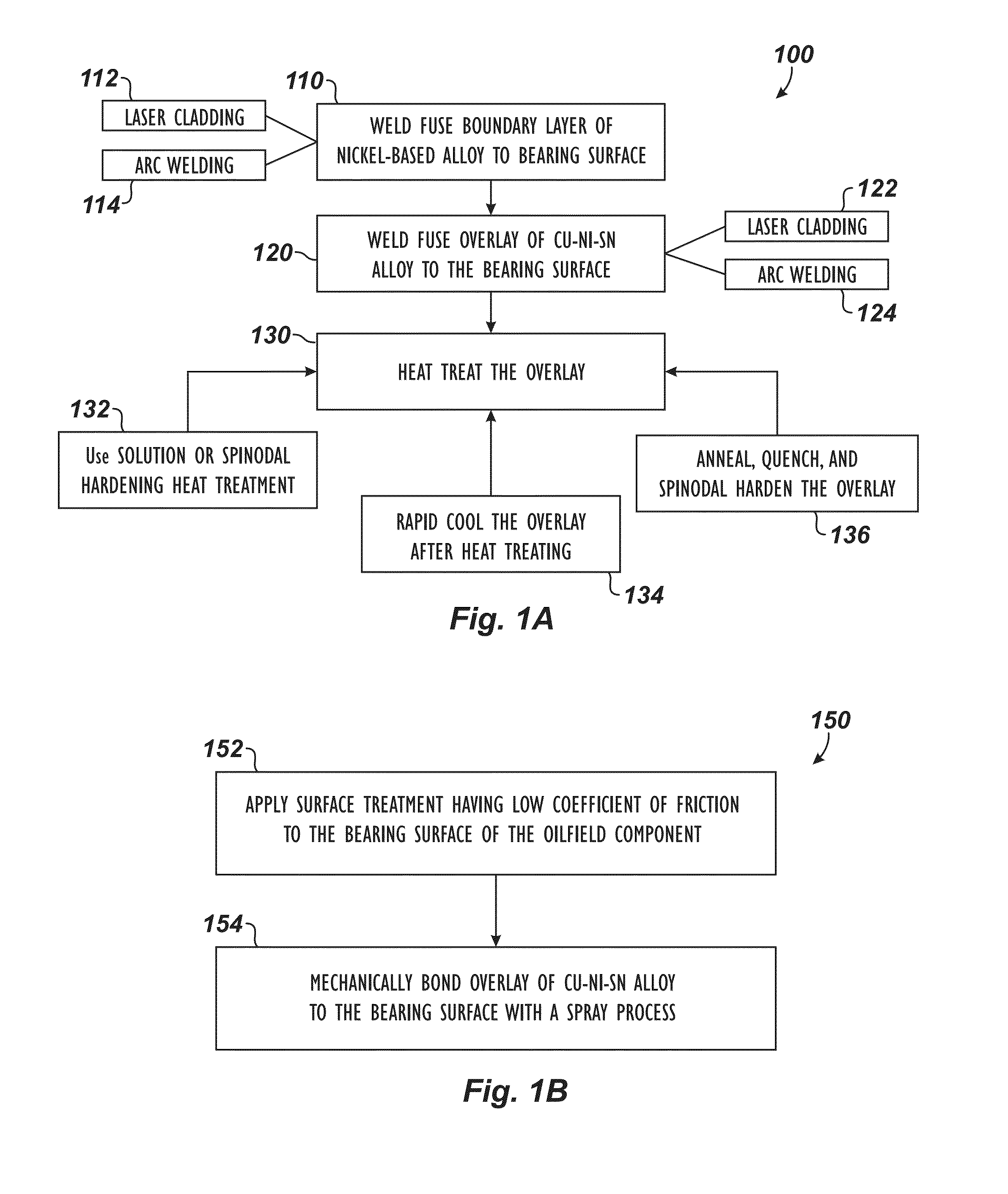
[0035]According to the present disclosure, surfacing techniques apply an overlay having a low coefficient of friction to a bearing surface using a weld fusion process on the bearing surface of a workpiece, such as an oilfield component or piece of oilfield equipment. The disclosed overlay is applied to the workpiece to improve the structure and hardness of the workpiece's bearing surface and can be used instead of (or in addition to) bearings, bushings, washers, and the like.

[0036]The disclosed overlay is composed primarily of a Cu—Ni—Sn alloy material. The preferred overlay composition contains roughly 15% nickel and 8% tin with the remaining balance being substantially copper. The copper-nickel-tin alloy for the disclosed overlay has good strength, anti-galling properties, and low coefficient of friction, making it useful as a low friction bearing material for equipment in the oilfield and other industries.

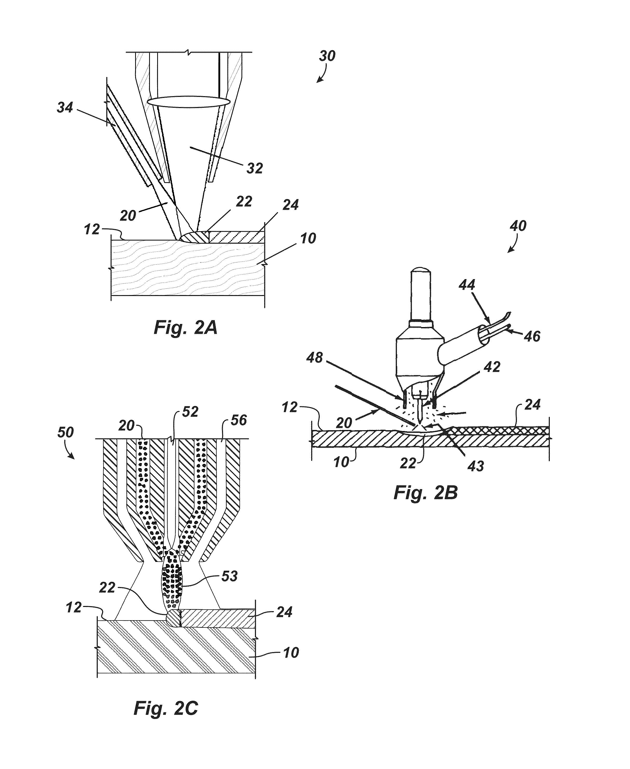
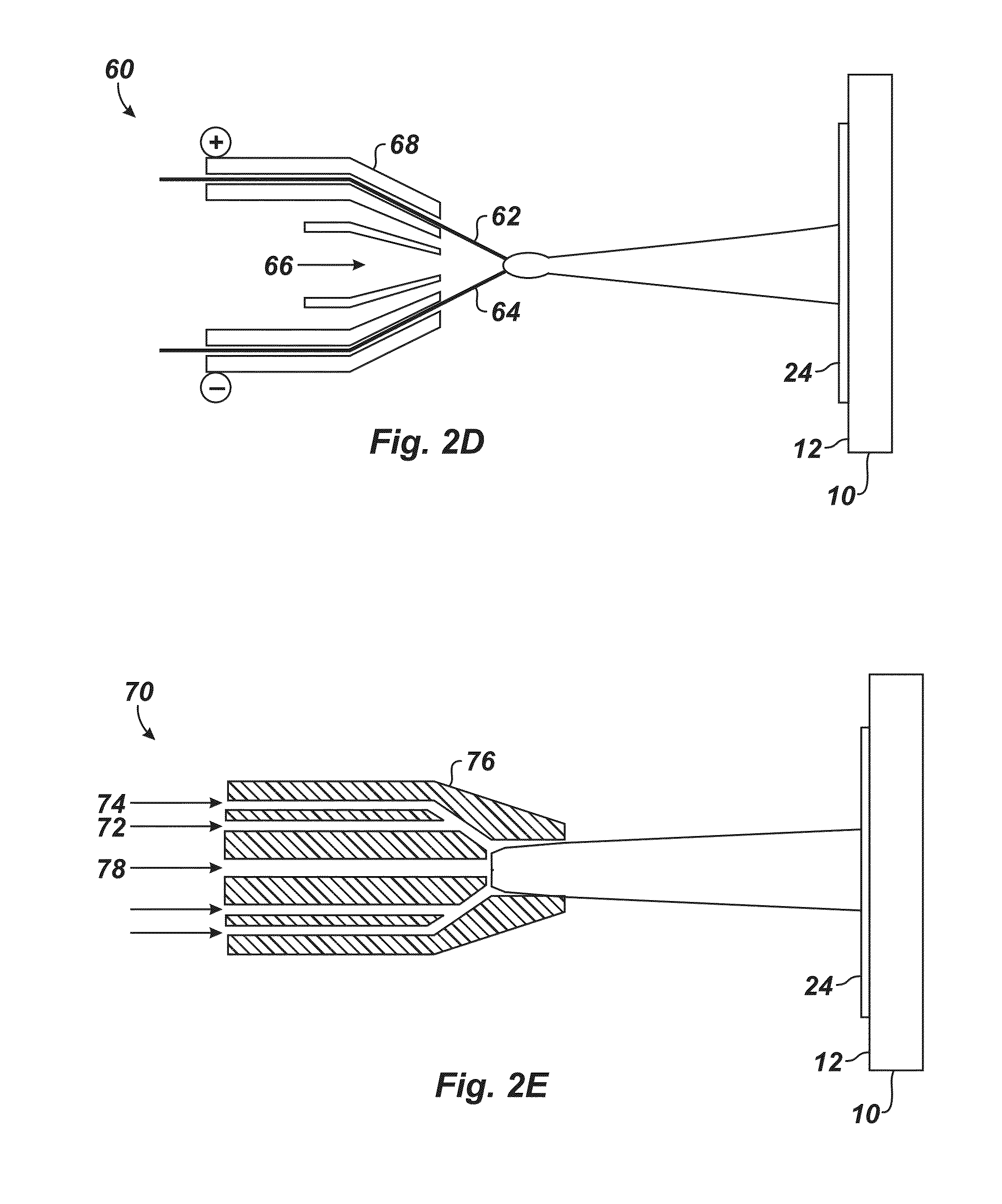
[0037]1. Weld Fusion Overlay Proc...


PUM

PropertyMeasurementUnit
thicknessaaaaaaaaaa
sizesaaaaaaaaaa
porosityaaaaaaaaaa

Abstract

A bearing surface of an oilfield component is treated by applying a surface treatment having a low coefficient of friction to the bearing surface of the oilfield component by weld fusing an overlay of a Cu—Ni—Sn alloy material to the bearing surface. Weld fusing the overlay of the Cu—Ni—Sn alloy material to the bearing surface can involve laser surface cladding the overlay of the Cu—Ni—Sn alloy material to the bearing surface, gas tungsten arc welding the overlay of the Cu—Ni—Sn alloy material to the bearing surface, or plasma tungsten arc welding the overlay of the Cu—Ni—Sn alloy material to the bearing surface.

Description

CROSS-REFERENCE TO RELATED APPLICATIONS[0001]This application claims the benefit of U.S. Prov. Appl. No. 61 / 892,889, filed 18 Oct. 2013, which is incorporated herein by reference.BACKGROUND OF THE DISCLOSURE[0002]Certain alloys are useful for bearings, bushings, and the like on equipment because the alloys have a low coefficient of friction, sufficient load bearing properties (e.g., hardness), and other suitable attributes. Copper beryllium alloys and nickel aluminum bronze alloys are examples of alloys used for bearings, bushings, and the like. The alloys can be used for various types of bearing surfaces. In the oil and gas industry, for example, the alloys can be used for rock bit bearings, bushings, and washers and can be used in downhole drilling tools, wellhead equipment, and BOP components.[0003]Another alloy that is used for various purposes is the copper-nickel-tin alloy class. This alloy class is typically produced as a strip or other solid form produced by a cast or powder...

Claims


Application Information

Patent Timeline
Patent Type & Authority Applications(United States)
IPC IPC(8): C10M103/04C23C30/00C23C4/18C23C4/12C23C4/08
CPCC10M103/04C23C4/125C23C30/00C23C4/18C23C4/127C23C4/08F16C2204/10F16C2223/42B23K9/04C22C9/06F16C33/121F16C33/14F16C2352/00F16C2223/46B23K9/167B23K10/027B23K26/147B23K26/34C23C4/131C23C4/129C23C4/134C23C24/106B23K35/302F16C33/125F16C33/127B32B15/01C22C9/00C22C9/02F16C2204/52
Inventor BADRAK, ROBERT P.
Owner WEATHERFORD TECH HLDG LLC
Why Eureka
Try Eureka