System and Method for Correcting the Focus of a Laser Beam

Active Publication Date: 2015-05-21
ASML NETHERLANDS BV
View PDF15 Cites 2 Cited by
  • Summary
  • Abstract
  • Description
  • Claims
  • Application Information

AI Technical Summary

Benefits of technology

This patent describes a system and method for minimizing focus errors of a laser beam during extreme ultraviolet (EUV) light production. The system includes a pressure controller that adjusts the deformation pressure of a focusing material to minimize the laser focus error and maximize measured power or divergence error of the laser beam. The focusing material is received at a low mass flow to avoid perturbing the reflective surface of the mirror. The technical effects of this patent include improved laser focus accuracy and efficiency in producing high-quality EUV light.

Problems solved by technology

Among possible issues affecting focus of the high power laser source on the target are collimation issues with the laser beam from the laser source, and aberrations introduced by the optical path including the focusing optic.
Collimation errors may also be introduced by other optical elements along the laser beam path.
Deviations from a high degree of collimation in the laser beam thereby affect the focus of the laser beam on the target droplet, which can result in reduced laser power on the target droplet, and reduced EUV production.
Focus errors in the final focus lens can spread the power of the laser source over a larger volume, reducing the power of the laser source delivered to the target droplet.
Reduced laser source power delivered to the target droplet can result in a reduced EUV power production.
While the resulting reflectance is high, for example, 98% to 99%, when used with multi-kilowatt high power CO2 lasers, such reflectance values still result in significant energy transfer from the laser beam into the reflective surface, causing heating.
Testing has revealed that such a VRM is not suitable for use prior to the final focus lens in the optical system of a LPP EUV light source, as the fluid flow through the VRM generates perturbations in the reflective surface which cause instability in focus of the laser beam.

Method used


Image

  • System and Method for Correcting the Focus of a Laser Beam
  • System and Method for Correcting the Focus of a Laser Beam
  • System and Method for Correcting the Focus of a Laser Beam

Examples


Embodiment Construction

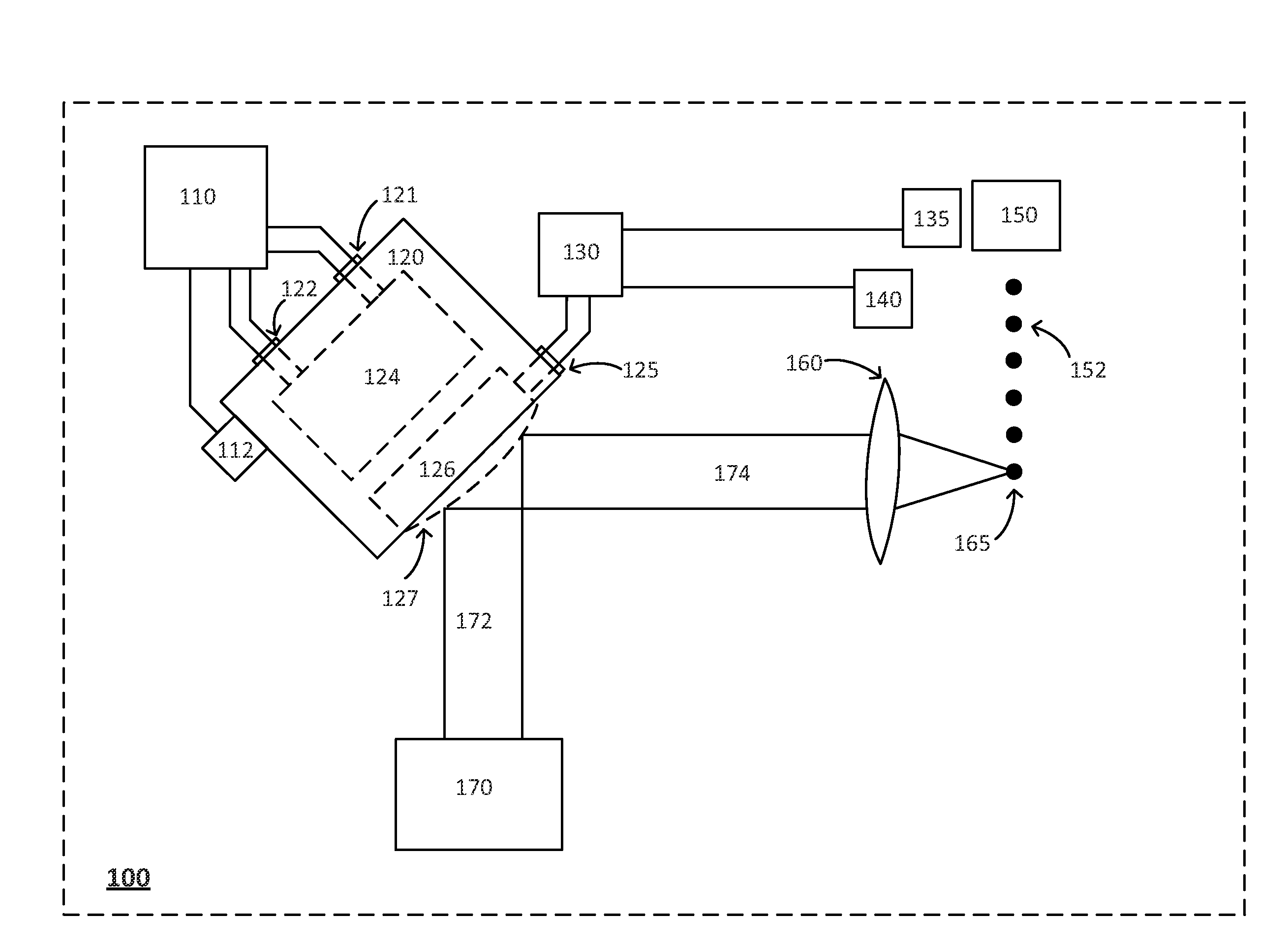
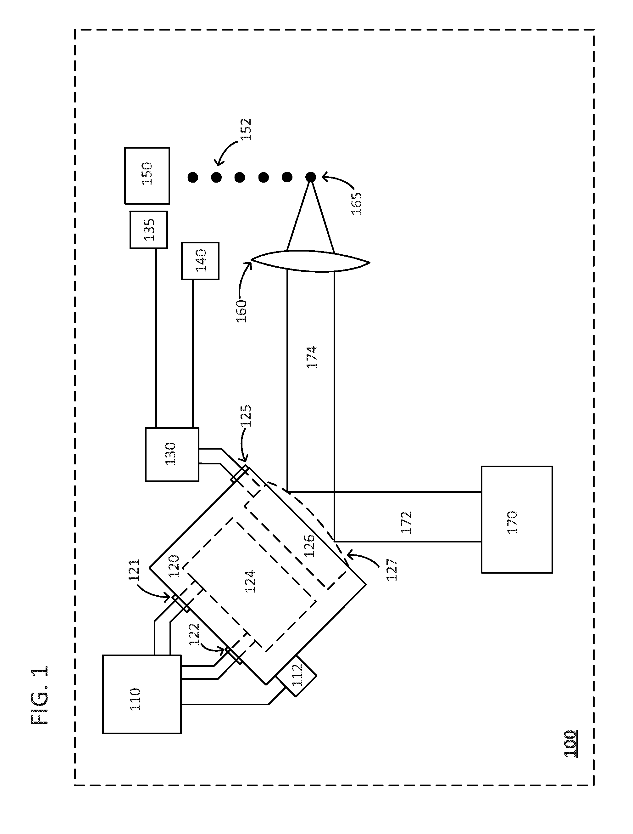
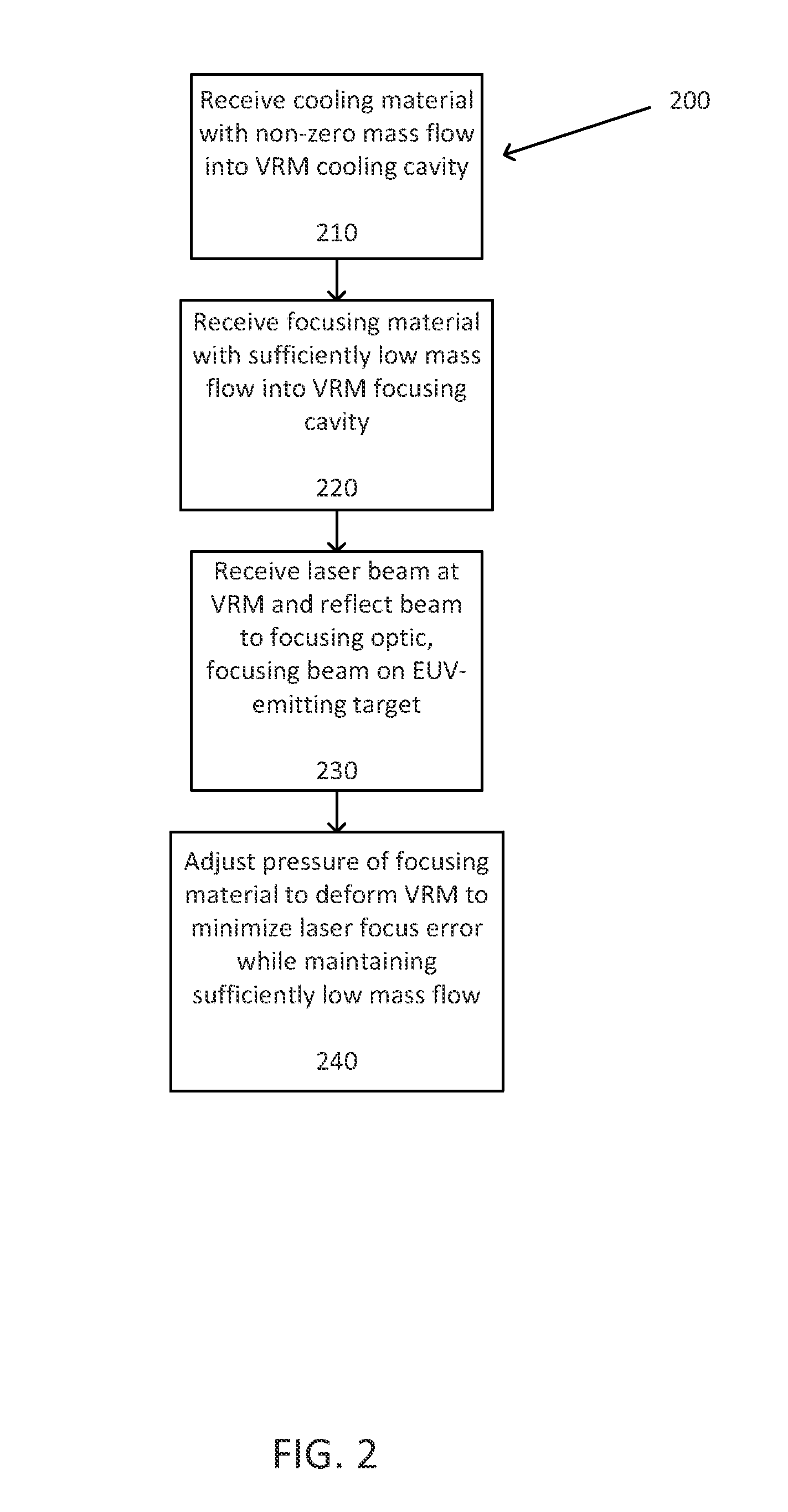
[0025]In the present approach, focusing errors of a laser source on an extreme ultraviolet (EUV) emitting target in a laser produced plasma (LPP) EUV light source such as collimation errors are corrected using a variable radius mirror (VRM) having a focusing cavity and a separate cooling cavity. Pressure of a focusing material in the focusing cavity deforms a reflective surface mounted to the focusing cavity, changing the radius of the reflective surface such that when the reflective surface of the VRM reflects light from a laser source to a focusing optic, focusing errors are minimized, thus delivering more laser energy to the EUV emitting target and maximizing EUV power. By maintaining the pressure of the focusing material at a sufficiently low mass flow at which perturbations are not introduced in the reflective surface, the VRM corrects focus without introducing perturbations into the reflective surface which would otherwise disturb focus of the laser beam.

[0026]FIG. 1 is a diag...


PUM


Abstract

Focus of a laser optical system can be corrected using a variable radius mirror having a focusing cavity and a separate cooling cavity. Pressure of a focusing material at a sufficiently low mass flow in the focusing cavity deforms a reflective surface mounted to the focusing cavity, changing its radius. Cooling material provided to the cooling cavity cools the variable radius mirror. A laser beam is reflected by the deformed reflecting surface to focusing optics, focusing the reflected laser beam on an EUV-emitting target, and minimizing a laser focus error by one or more of: maximizing a measured EUV power or minimizing a measured laser beam divergence. Providing focusing material at a deformation pressure and at a sufficiently low mass flow, and providing a separate cooling cavity, avoids perturbations in the reflective surface which would otherwise affect laser beam focus.

Description

BACKGROUND OF THE INVENTION [0001]1. Field of the Invention[0002]The present invention relates generally to laser technology for photolithography, and, more particularly, to optimization of extreme ultraviolet (EUV) light production through correction of the focus of a laser beam used to produce the EUV light.[0003]2. Description of the Prior Art[0004]The semiconductor industry continues to develop lithographic technologies which are able to print ever-smaller integrated circuit dimensions. Extreme ultraviolet (EUV) light (also sometimes referred to as soft x-rays) is generally defined to be electromagnetic radiation having wavelengths of between 10 and 110 nanometers (nm). EUV lithography is generally considered to include EUV light at wavelengths in the range of 10-14 nm, and is used to produce extremely small features (e.g., sub-32 nm features) in substrates such as silicon wafers. These systems must be highly reliable and provide cost-effective throughput and reasonable process ...

Claims


Application Information

Patent Timeline
IPC IPC(8): G02B5/08G02B27/40H05G2/00
CPCG02B5/0891G02B27/40H05G2/008G02B7/1815G02B26/0825
Inventor PATE, CHRISTOPHER PAULARCAND, JASON MICHAEL
Owner ASML NETHERLANDS BV
Why Eureka
Try Eureka