Configurations and methods of flexible co2 removal

a co2 removal and flexible technology, applied in the field of acid gas removal, can solve the problems of high co2 content gas fields that remain undeveloped, membrane elements are prone to fouling and material degradation, and gas fields with high co2 content are often considered uneconomical

Active Publication Date: 2015-06-18
FLUOR TECH CORP
View PDF2 Cites 21 Cited by
  • Summary
  • Abstract
  • Description
  • Claims
  • Application Information

AI Technical Summary

Benefits of technology

[0017]Consequently, the inventors also contemplate a plant for acid gas removal from a hydrocarbonaceous feed gas, typically comprising at least 20 mol % CO2. Especially contemplated plants are fluidly coupled to a feed gas source that provides a hydrocarbonaceous feed gas comprising H2S and CO2 at a pressure of at least 300 psig. An H2S removal unit then selectively removes H2S from the feed gas to produce an H2S depleted feed gas, and a first and a second absorber are fluidly coupled in series to the H2S removal unit and remove CO2 from the H2S depleted feed gas using a semi-lean generated from the second absorber and an ultralean solvent generated from the stripping section, respectively, and thereby produce a product gas (preferably having CO2 content of 500 ppmv to 0.5 mol % CO2), and a rich solvent. A plurality of pressure reduction stages subsequently receive and reduce pressure of the rich solvent to generate work, a CO2 stream, and a cooled flashed solvent, and first and second heat exchangers use the cooled flashed solvent to cool the H2S depleted feed gas and the semi-lean solvent. Finally, a stripping unit strips the flashed solvent with dried air (preferably having a water dew point of equal or less than −40° F.) to produce the ultralean solvent, and a conduit is installed to combine a portion of the ultralean solvent with the H2S depleted feed gas. As used herein, and unless the context dictates otherwise, the term “coupled to” is intended to include both direct coupling (in which two elements that are coupled to each other contact each other) and indirect coupling (in which at least one additional element is located between the two elements). Therefore, the terms “coupled to” and “coupled with” are used synonymously.
[0018]Most preferably, the solvent is a physical solvent (e.g., propylene carbonate, tributyl phosphate, normal methylpyrrolidone, a dimethyl ether of polyethylene glycol, and / or polyethylene glycol dialkyl ethers), and the H2S removal unit removes H2S using a H2S selective solvent or a sulfur scavenger adsorbent. In is also contemplated that the plurality of pressure reduction stages is configured such that at least 85% of the CO2 content in the rich solvent is removed from the solvent at atmospheric pressure.
[0019]Various objects, features, aspects and advantages of the inventive subject matter will become more apparent from the following detailed description of preferred embodiments, along with the accompanying drawing figures in which like numerals represent like components.

Problems solved by technology

Typically, gas plants are designed to meet pipeline gas transportation specifications on inerts, sulfur, hydrocarbons, and water dewpoint requirements and not designed to handle high CO2 content gases (e.g., 50 mol % or higher).
Gas fields with high CO2 content are often considered uneconomical as technologies for high CO2 removal or variable CO2 removal are considered difficult; and consequently such high CO2 gas fields remained undeveloped.
However, membrane elements are prone to fouling and material degradation from gas contaminants and therefore must be monitored and periodically replaced.
While initial capital outlay may be lower than with other processes, replacement costs of the membranes add up over the life of the plant.
In terms of performance, single stage membrane separators are relatively non-selective and often produce a CO2 waste stream with a high hydrocarbon content, which may not meet environmental permits on greenhouse gas.
Additional processing equipment may be used to improve the membrane performance (e.g., multiple stages of membrane separators with inter-stage recompression and recycle), however, such equipment will increase the cost and footprint of the system, rendering membrane separation economically unattractive.
However, while use of chemical solvent (e.g. amine) systems may be advantageous, particularly in treating low CO2 content gases, there are unsurmountable difficulties when applied to treat high CO2 fields.
Even with activated or promoted tertiary amine such as MDEA, the heat requirement for solvent regeneration is significant for high CO2 content gases, which may consume significant amounts of the treated gas for heating, making such development once again uneconomical.
Furthermore, the amine processes typically operate at relatively high temperature such that equipment and piping are prone to failure from corrosion and foaming problems.
Yet another disadvantage of amine systems is that the treated gas and CO2 streams are saturated with water, which must be dried with a drying unit to meet pipeline specifications.
However, cryogenic refrigeration is very costly, and low temperature solvent also co-absorbs a significant amount of hydrocarbons, resulting in high hydrocarbons losses.
Therefore, while the methanol process is common in syngas treating, they are rarely used in natural gas plants.
Nevertheless, there are limitations on these processes as they require a vacuum flash stage to produce the lean solvent which is energy intensive.
Moreover, where vacuum stages are omitted, non-vacuum flash stages will not produce an ultralean solvent to meet stringent CO2 specifications.
Therefore, it should be appreciated that most known solvent processes lack an efficient heat exchange integration configuration, and often require significant refrigeration and / or high solvent circulation, and sometimes require heat for solvent regeneration.
Even with significant fuel and power consumption, these processes cannot fully regenerate the solvent to an ultralean level that can be used to treat high CO2 feed gas to meet a low CO2 specification on carbon capture.
Thus, although various configurations and methods are known to remove CO2 from a feed gas, all or almost all of them suffer from one or more disadvantages.

Method used


Image

  • Configurations and methods of flexible co2 removal
  • Configurations and methods of flexible co2 removal
  • Configurations and methods of flexible co2 removal

Examples


Embodiment Construction

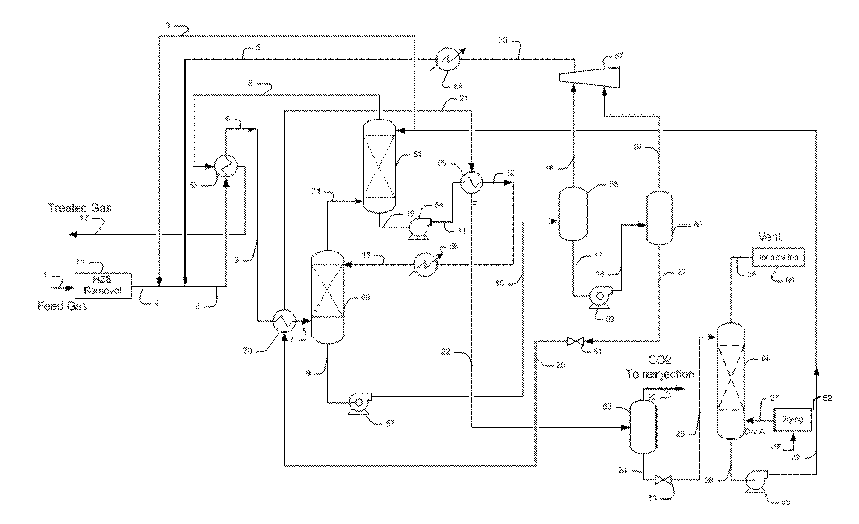
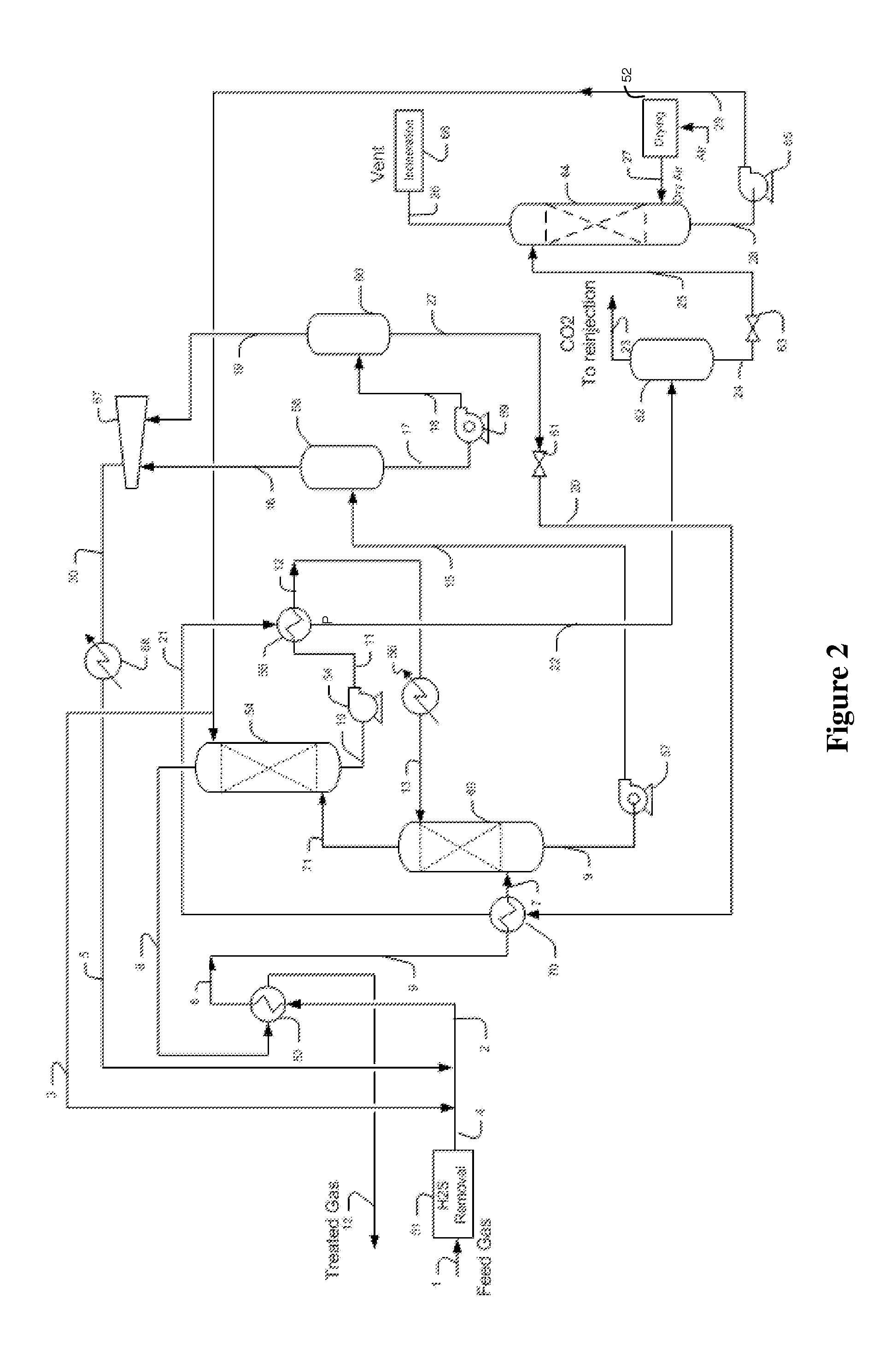
[0023]The inventor has discovered that acid gases, and predominately CO2, can be removed in a conceptually simple and effective manner to meet stringent CO2 specification of 500 ppmv to 0.5 mol % from a feed gas that contains H2S and variable CO2 content ranging from 5 mol % to 60 mol % CO2 at pressures ranging from 300 psig to 1100 psig, or even higher.

[0024]In especially preferred methods, H2S is preferentially, and more typically selectively removed from the feed gas prior to CO2 removal that is carried out in one or more absorbers. Deep solvent regeneration is achieved in an economic manner by dry air stripping, which will allow the circulating solvents to remain in a dry state. Such regeneration and solvent chilling (e.g., to −15° F. to −25° F.) in combination with sequential acid gas removal is particularly effective to maximize solvent loading and to minimize solvent circulation, and to allow use of the same plant to treat varying concentrations of CO2 in the feed gases, whil...


PUM

PropertyMeasurementUnit
pressureaaaaaaaaaa
water dew pointaaaaaaaaaa
temperatureaaaaaaaaaa

Abstract

A plant includes a pretreatment unit for H2S removal and air dehydration, and at least two absorbers that receive a feed gas at a pressure of at least 300 psig with variable CO2 content (e.g., between 5 to 60 mol %), wherein the feed gas is scrubbed in the absorbers with an ultralean and a semi-lean physical solvent, respectively, at low temperatures to at least partially remove the CO2 from the feed gas. Such configurations produces a low CO2 dry treated gas and a H2S-free CO2 for sequestration while advantageously providing cooling by expansion of the rich solvent that cools the semi-lean solvent and the feed gas, wherein an ultralean solvent is produced by stripping using dry air.

Description

[0001]This application claims priority to copending U.S. provisional application with the Ser. No. 61 / 915,173, filed 12 Dec. 2013.FIELD OF THE INVENTION[0002]The field of the invention is removal of acid gases from a feed gas, and particularly relates to CO2 removal of variable high CO2 content feed gas.BACKGROUND OF THE INVENTION[0003]The background description includes information that may be useful in understanding the present invention. It is not an admission that any of the information provided herein is prior art or relevant to the presently claimed invention, or that any publication specifically or implicitly referenced is prior art.[0004]Acid gas removal from various gas streams, especially removal of CO2 from natural gas streams has become an increasingly important process as the sweet gas reservoirs are being depleted and the high CO2 content fields are being developed. There are relatively large natural gas resources untapped in the world (e.g., Alaska, Continental North ...

Claims


Application Information

Patent Timeline
Patent Type & Authority Applications(United States)
IPC IPC(8): C10L3/10B01D53/18B01D53/14
CPCC10L3/104C10L3/103B01D53/1406B01D53/1425B01D53/1462B01D2252/205B01D53/18B01D53/1437B01D2252/2025B01D2252/2056B01D2252/2026B01D53/1493B01D53/1431B01D53/1475B01D2252/20B01D2252/20468B01D2256/24B01D2257/304C10L2290/06C10L2290/08C10L2290/48C10L2290/541C10L2290/545Y02C20/40
Inventor MAK, JOHN
Owner FLUOR TECH CORP
Why Eureka
Try Eureka