Draft Tube Fluidized Bed Reactor for Deposition of Granular Silicon

a technology of fluidized bed reactor and granular silicon, which is applied in the direction of silicon compounds, lighting and heating apparatus, coatings, etc., can solve the problems of reactor damage, reduced volume otherwise available for reactants, and forced shutdown and cleanout and/or rebuilding, etc., and achieves reduced temperature limitations and contamination. , the effect of reducing the volume of voids

Active Publication Date: 2015-07-02
HAZELTINE BRUCE
View PDF2 Cites 8 Cited by
  • Summary
  • Abstract
  • Description
  • Claims
  • Application Information

AI Technical Summary

Benefits of technology

[0011]The vessel for this design can be made with several materials known to those skilled in the art. Preferably, the vertical sides and top of the reactor are made of carbon fiber / graphite composite (commonly referred as carbon / carbon composite, or simply CC), that is silicon carbide (SIC) coated. The bottom of the vessel and distributor are preferably made of monolithic graphite. By using these materials, problems of temperature limitations and contamination are substantially reduced versus using metallic components employed in some designs. The CC material is strong and can be fabricated in diameters up to at least 1 meter. If necessary, pieces can be joined end to end and sealed with a gasketted connection. When wall deposition of silicon occurs to an unacceptable extent to continue normal operation, the deposition can be melted off and drained to a safe location designed for this purpose.
[0012]The reactor of this invention constructed of graphite, CC and ceramic materials is enclosed in a metallic pressure vessel for secondary containment. This enables the reactor to be operated at pressures well above atmospheric pressure allowing greater gas mass flow rates at minimum fluidization velocities. By operating at elevated pressure and near minimum fluidization velocity, low void volumes can be achieved reducing dust formation when compared to beds with greater void volumes.

Problems solved by technology

The problems routinely encountered are: 1) Formation of dust due to homogeneous nucleation of the silicon bearing gas and subsequent loss of valuable raw material; 2) Silicon deposition on the wall and internals of the FBR reducing the volume otherwise available for reactants and ultimately forcing shutdowns and cleanouts and / or rebuilds.
If the FBR is made of brittle materials such as graphite or quartz, the differential coefficient of thermal expansion (CTE) between silicon deposited on the wall and the wall itself is likely to lead to reactor damage; 3) Inability to create the scenario where the reactive gas is sufficiently cold to avoid homogeneous nucleation (dust formation) and silicon beads hot enough to make shiny polycrystalline beads as opposed to amorphous silicon and / or a dusty surface that forms at lower bead temperatures; 4) Hydrogen or other gas inclusions exist within the silicon bead after deposition.
A dense bead free of H2 or other gases is desired to avoid problems in downstream processing; 5) Finding suitable materials of construction for the FBR that are strong enough to resist breakage and which do not also contaminate the product is a continual challenge.
For instance, metallic FBR's are durable and not susceptible to damage from differential CTE's but to date, no one has been able to avoid significant contamination of the product with a metal walled FBR; 6) Difficulties maximizing bead size; 7) Keeping bead size within an acceptably small range or particle size distribution; 8) preventing deposition within the feed nozzles where a silicon containing gas is fed.

Method used


Image

  • Draft Tube Fluidized Bed Reactor for Deposition of Granular Silicon
  • Draft Tube Fluidized Bed Reactor for Deposition of Granular Silicon
  • Draft Tube Fluidized Bed Reactor for Deposition of Granular Silicon

Examples


constructive example 1

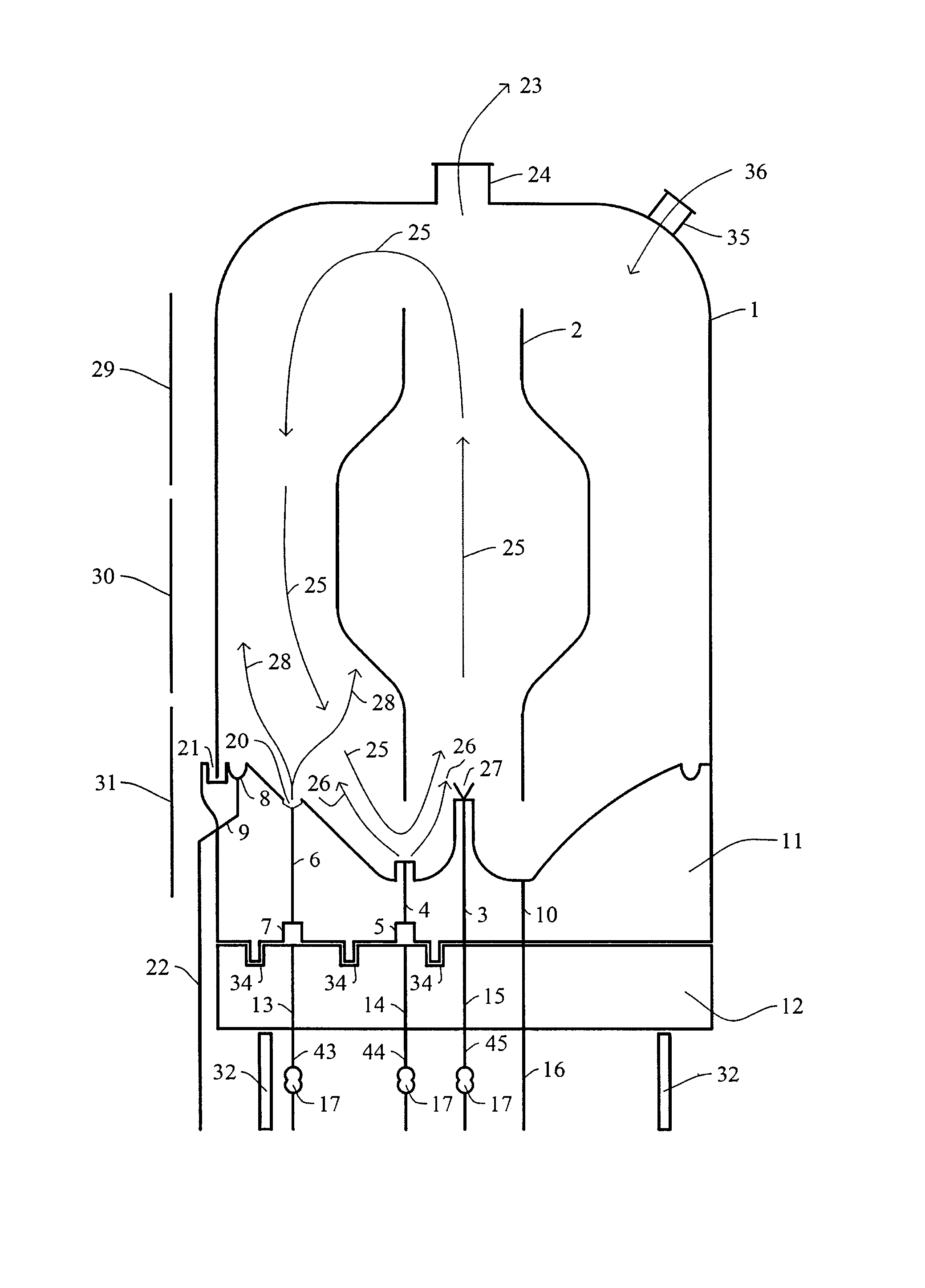
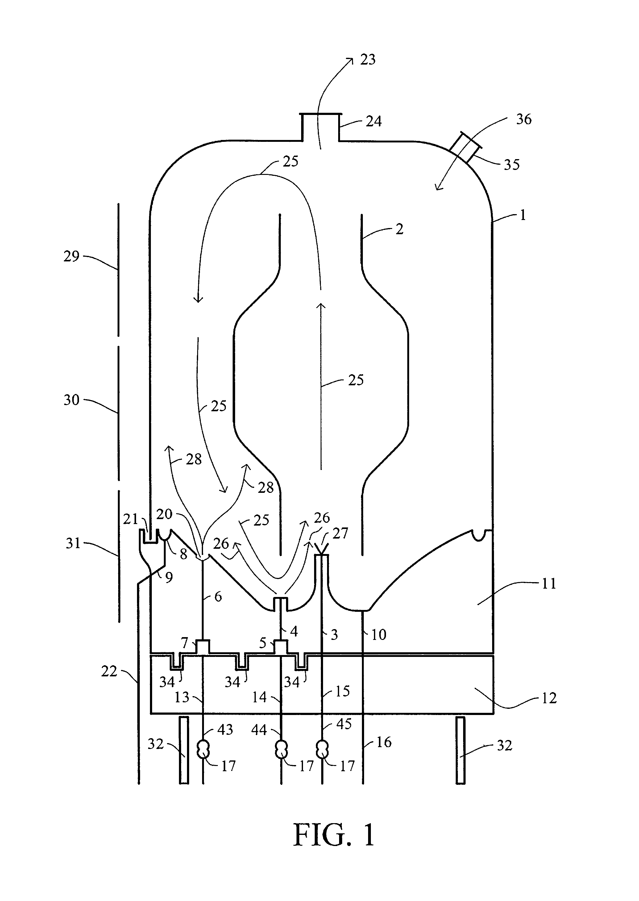
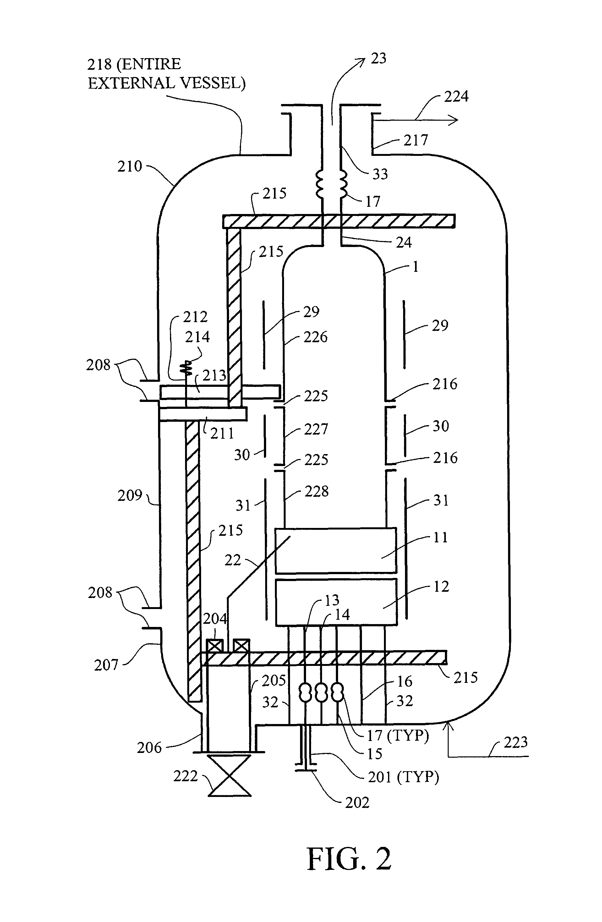
[0076]The draft tube FBR was modeled using chemical engineering simulation software widely used in industry (Chemcad, Version 6, provided by Chemstations, 3100 Wilcrest Drive, Suite 300, Houston, Tex., USA and Aspenplus, Version 8, provided by AspenTech, 20 Crosby Drive, Bedford, Mass., USA). Physical properties, thermodynamic models, and equations of state known by those skilled in the art to be sufficiently accurate for industrial applications were used. Feed gas through ports 6 was modeled at 15 mol % SiH4, balance H2 at a mass flow of 659 kg / hr at 165° C. Feed gas through port(s) 3 was modeled at 12 kg / hr H2 at 600° C. Pressure was 5 bar. Net flow upward through the draft tube was 18831 kg / hr at a volumetric rate of 1.03 ft3 / S at 706° C. 293 kg / hr exited the RXR in stream 23 as 1.2 mol % SiH4, balance H2, at 793° C. The silicon rising through the draft tube (18819 kg / hr at 706° C.) descended in the annular space and 582 kW heat was added from heaters 29, 30 raising the temperatu...


PUM

PropertyMeasurementUnit
inner diameteraaaaaaaaaa
gas flow rateaaaaaaaaaa
diameteraaaaaaaaaa

Abstract

A granular fluidized bed reactor (FBR) for production of high purity silicon is described. The FBR uses a draft tube to promote internal circulation while minimizing voids in the fluidized bed, one significant cause of dust formation. The FBR design has geometries to minimize reactive gas concentration within the draft tube and imposes a desirable circulation pattern in operation. A portion of the FBR wall above a reactive zone provides heat input to maximize deposition on silicon beads while minimizing wall deposition. The FBR is made of carbon composite, ceramic, and graphite materials in a design to minimize contamination and enable silicon deposits to be melted out.

Description

CROSS-REFERENCE TO RELATED APPLICATIONS[0001]This application claims the benefits of U.S. Provisional Application No. 61 / 920,945, filed Dec. 26, 2013, the disclosure of which is hereby incorporated by reference in its entirety including all figures, tables and drawings.STATEMENT REGARDING FEDERALLY SPONSORED RESEARCH OR DEVELOPMENT[0002]Not applicable.REFERENCE TO SEQUENCE LISTING, A TABLE, OR A COMPUTER PROGRAM LISTING COMPACT DISC APPENDIX[0003]Not applicable.FIELD OF THE INVENTION[0004]This invention relates generally to a reactor and process to make high purity granular silicon in a chemical vapor deposition (CVD) fluidized bed reactor (FBR) where that FBR contains a draft tube. The reactor is fed a silicon containing gas and preferably makes use of graphite and carbon / carbon composite materials of construction.BACKGROUND OF THE INVENTION[0005]Chemical vapor deposition (CVD) reactors are used to produce polycrystalline silicon (polysilicon), the key raw material used in the manu...

Claims


Application Information

Patent Timeline
Patent Type & Authority Applications(United States)
IPC IPC(8): B01J8/08
CPCB01J8/08B01J8/1827B01J8/1854B01J8/1872B01J8/34C01B33/029C23C16/442
Inventor HAZELTINE, BRUCE
Owner HAZELTINE BRUCE
Why Eureka
Try Eureka