Electron source for an rf-free electronmagnetostatic electron-induced dissociation cell and use in a tandem mass spectrometer

a technology of electron-induced dissociation cell and electron source, which is applied in the direction of particle separator tube details, instruments, separation processes, etc., can solve the problems of limiting the informational output of experiments, shackling the design and execution of experiments, and limiting the efficiencies of electron-induced fragmentation processes, so as to increase the reaction efficiency, increase the overlap, and increase the reaction efficiency

Active Publication Date: 2015-07-02
THE STATE OF OREGON ACTING BY & THROUGH THE OREGON STATE BOARD OF HIGHER EDUCATION ON BEHALF OF OREGON STATE UNIV
View PDF3 Cites 7 Cited by
  • Summary
  • Abstract
  • Description
  • Claims
  • Application Information

AI Technical Summary

Benefits of technology

[0008]In particular, in one of its aspects the present disclosure describes central principles for designing embodiments of electron sources that can substantially increase the overlap between the volumes occupied by electrons and a beam of ions and, thereby, increase the reaction efficiencies of any electron-induced dissociation reaction. In this regard, the present invention provides important advances over the inventors' prior work as disclosed in the Published U.S. patent application No. 2011 / 0233397, which is incorporated herein by reference in its entirety. In particular, the present disclosure describes how the cavities of EMS cells might preferably be designed to efficiently trap electrons produced from internal sources or external sources, as well as how such sources might preferably be shaped and placed in order to increase the reaction efficiencies of any electron-induced dissociation process in the cell.

Problems solved by technology

From a manufacturing point of view, this situation stifles development of new instrumentation, software, and methodology; from a research point of view, it shackles the design and execution of experiments or limits their informational output.
], the efficiencies of electron-induced fragmentation processes are fundamentally limited; electrons cannot be trapped at all in linear RF-based devices and only in small numbers in three-dimensional RF-traps (e.g., FT ICR cells).
Consequently, there is no practicable way for increasing the density of electrons in reaction cells of these types.
This is a major disadvantage for two practical reasons.
First the charged-particle capacity of an RF-based device is relatively small; consequently, it is difficult to achieve high yields of product-ions from electron-induced dissociation reactions, which require that a reactant's density (i.e., the number of particles per unit volume) be as high as possible.
Second, in terms of detection limit, resolution, and mass accuracy in analyses of organic compounds, FT ICR mass spectrometers are arguably the most powerful in existence; unfortunately, they are also the most expensive to purchase, difficult and expensive to operate and maintain, and ill-suited to the high throughput analyses frequently encountered in proteomics.
This, however, is fundamentally impossible to accomplish in an FT ICR cell, and because of fundamental constraints on the latter's geometry and operation, the prospects for improving this circumstance are poor.
However, dispenser cathodes cannot tolerate vacuum pressures higher than 10−7 Torr.
There are, however, technical obstacles that must be overcome in order for these electrons to occupy the same volume as the ions with which the electrons must react.

Method used


Image

  • Electron source for an rf-free electronmagnetostatic electron-induced dissociation cell and use in a tandem mass spectrometer
  • Electron source for an rf-free electronmagnetostatic electron-induced dissociation cell and use in a tandem mass spectrometer
  • Electron source for an rf-free electronmagnetostatic electron-induced dissociation cell and use in a tandem mass spectrometer

Examples


experiment 1

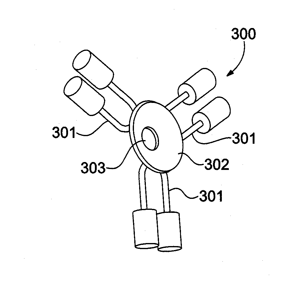
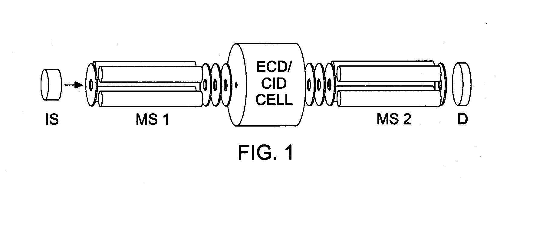
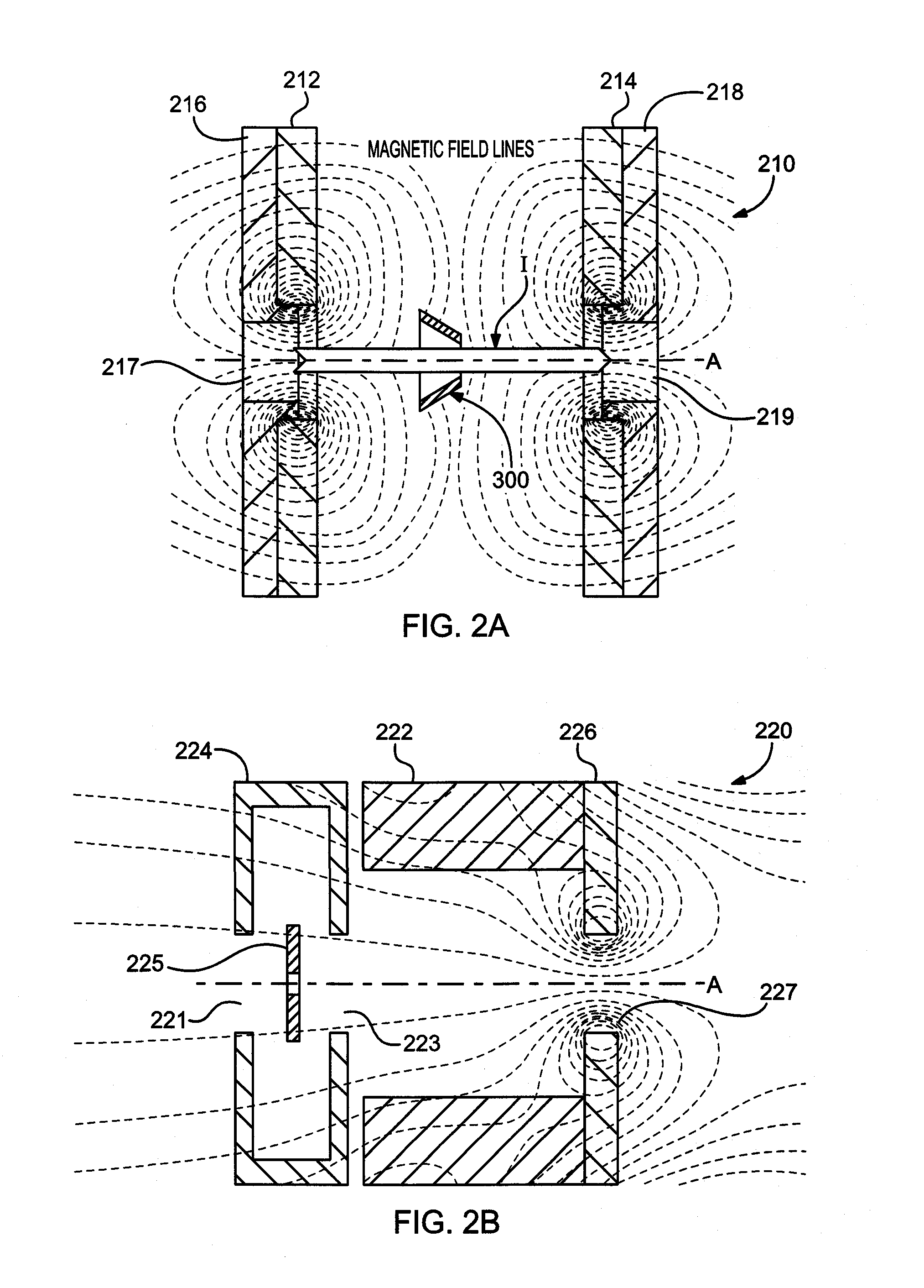
[0051]A triple quadrupole (Q-q-Q) Finnigan TSQ 700 mass spectrometer was converted to a Q-ECD-Q instrument (cf. FIG. 1) having a tantalum cone 302a, FIG. 3C, located concentric with the cell's axis at the ion-entrance, which served as the source of electrons. Cones 302a with two different apex angles were manufactured, 45° and 60°. For the 45° cone, the diameter at the base was 5 mm and the diameter of the hole 303a was 3 mm; for the 60° cone, the diameter at the base was 3 mm and the diameter of the hole 303a was 1 mm. Three pairs of tantalum heating wires 301a were attached to the external side of the cone 302a, and the emitter 300a was used as the emitter 225 in the cell 220 of FIG. 2B, and was fixed in a molybdenum holder 224 with an entrance aperture 221 and exit aperture 223 for passage of ions and electrons. The cell 220 comprised an electromagnet 222, which contained copper wire of 1.2 mm diameter spooled on a titanium bobbin of 70 mm outer diameter, 6.0 mm inner diameter, a...

experiment 2

[0054]In a second experiment in accordance with the present invention, the cell 220 of FIG. 2B was used with an electron emitter 225 fabricated in the form of a flat disc 502, FIGS. 5A, 5B, and with the electromagnet 222, because the electromagnet 222 can provide a magnetic field with lines perfectly perpendicular to the surface of disc 502 (Condition 1, requirement for the best guiding electrons from emitter to the axis where ions are). Flat disc emitters 500 can be made two to three times thinner than cone-shaped emitters 300 and, thus, require less power and generate correspondingly less heat radiation. The heating current may be provided through the disc emitter 500.

[0055]Two exemplary forms of emitters in accordance with the present invention were created that retained the advantages of both a loop filament (viz. small bulk / size, low power consumption, tolerance to low vacuum, and low cost) and an indirectly heated dispenser cathode (viz. large emitting area, no voltage drop th...


PUM


Abstract

An electron source for electron-induced dissociation in an RF-free electromagnetostatic cell for use installation in a tandem mass spectrometer is provided. An electromagnetostatic electron-induced dissociation cell may include at least one magnet having an opening disposed therein and having a longitudinal axis extending through the opening, the magnet having magnetic flux lines associated therewith, and an electron emitter having an electron emissive surface comprising a sheet, the emitter disposed about the axis at a location relative to the magnet where the electron emissive surface is substantially perpendicular to the magnetic flux lines at the electron emissive surface.

Description

GOVERNMENT LICENSE RIGHTS[0001]This invention was made with government support under Grant No. CHE0924027 awarded by the National Science Foundation, by Grant No. RO1 RR026275-02 awarded by the National Institutes of Health, and by Grant No. E500210 awarded by the National Institute of Environmental Health Science. The government has certain rights in the invention.FIELD OF THE INVENTION[0002]The present invention relates generally to radio-frequency-free hybrid electrostatic / magnetostatic cells and methods for dissociating ions in mass spectrometers, and more particularly, but not exclusively, to internal electron source configurations for use with such cells and methods.BACKGROUND OF THE INVENTION[0003]Academic and commercial instrument designers alike have come to over rely on strictly electrostatically- and RF-driven devices for dissociating ions in tandem mass spectrometers, roughly half of which are analyzer-dependent. From a manufacturing point of view, this situation stifles...

Claims


Application Information

Patent Timeline
Patent Type & Authority Applications(United States)
IPC IPC(8): H01J49/14H01J49/26H01J49/08
CPCH01J49/147H01J49/26H01J49/08H01J49/0054H01J49/062
Inventor BAROFSKY, DOUGLAS F.VOINOV, VALERY G.
Owner THE STATE OF OREGON ACTING BY & THROUGH THE OREGON STATE BOARD OF HIGHER EDUCATION ON BEHALF OF OREGON STATE UNIV
Why Eureka
Try Eureka