Lithographic printing plate precursor and plate making method of lithographic printing plate
a technology precursor, which is applied in the direction of lithography, photosensitive materials, instruments, etc., to achieve good development properties and maintain the printing durability of lithographic printing pla
- Summary
- Abstract
- Description
- Claims
- Application Information
AI Technical Summary
Benefits of technology
Problems solved by technology
Method used
Image
Examples
examples
[0192]The invention will be described in more detail with reference to the following examples, but the invention should not be construed as being limited thereto. With respect to the polymer compounds used in the examples, unless otherwise particularly defined, a molecular weight means a weight average molecular weight (Mw) calculated in terms of polystyrene measured by GPC method and a ratio of repeating units is indicated in mole percent.
[Synthesis Example of Modified Cellulose]
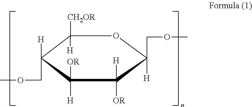
[0193]Formulation: Into a flask equipped with a stirring device and a cooling pipe were put 10.0 g of cellulose, 1.2 g of sodium hydroxide and 35.5 g of N-ethylpyrrolidone, and the inner temperature was set to 90° C. Then, 4.0 g of butanesultone was added dropwise while taking care of temperature rise, and after the dropwise addition the mixture was reacted under stirring at 90° C. for 12 hours to synthesis a modified cellulose described in Table 1 below for use in Example 1.
[0194]Modified celluloses for us...
examples 1 to 5
1. Production of Lithographic Printing Plate Precursor
(1) Production of Support
[0195]An aluminum plate (material: MS A 1050) having a thickness of 0.3 mm was subjected to a degreasing treatment at 50° C. for 30 seconds using a 10% by weight aqueous sodium aluminate solution in order to remove rolling oil on the surface thereof and then grained the surface thereof using three nylon brushes embedded with bundles of nylon bristle having a diameter of 0.3 mm and an aqueous suspension (specific gravity: 1.1 g / cm3) of pumice having a median size of 25 μm, followed by thorough washing with water. The plate was subjected to etching by immersing in 25% by weight aqueous sodium hydroxide of 45° C. for 9 seconds, washed with water, then immersed in a 20% by weight nitric acid solution at 60° C. for 20 seconds, and washed with water. The etching amount of the grained surface was about 3 g / m2.
[0196]Then, using an alternating current of 60 Hz, an electrochemical roughening treatment was continuou...
examples 6 to 18
[0213]Photosensitive solution (2) shown below was coated on Support (2) described above based on the method described in the formation of image-recording layer in Example 1 to obtain lithographic printing plate precursors for Examples 6 to 18 having an image-forming layer having a dry coating amount of 1.0 g / m2, respectively.
[0214]
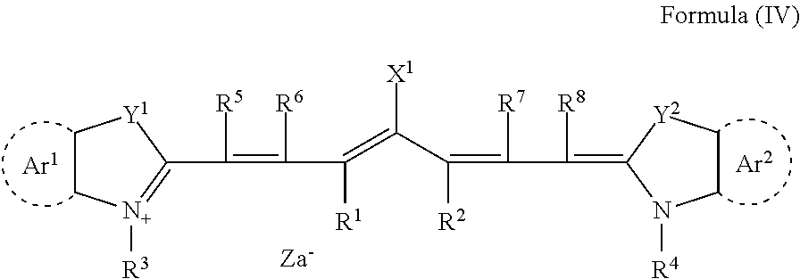
Aqueous dispersion (1) of polymer fine particle20.0 g Infrared absorbing agent (2) having structure shown below0.2 gRadical generator (IRGACURE 250, produced by BASF)0.5 gSulfonic acid-modified cellulose shown in Table 10.3 gOrganic borate (A) having structure shown above0.25 g Polymerizable compound (SR-399, produced by Sartomer Co.)1.50 g Mercapto-3-triazole0.2 gBYK 336 (produced by BYK-Chimie GmbH)0.4 gELVACITE 4026 (produced by Ineos Acrylica Inc.)2.5 gn-Propanol55.0 g 2-Butanone17.0 g
[0215]The compounds indicated using their trade names in the composition described above are as shown below.
IRGACURE 250: (4-Methoxyphenyl)[4-(2-methylpropyl)phenyl]iodo...
PUM
| Property | Measurement | Unit |
|---|---|---|
| structure | aaaaa | aaaaa |
| oleophilic | aaaaa | aaaaa |
| hydrophilic | aaaaa | aaaaa |
Abstract
Description
Claims
Application Information
 - R&D
- Intellectual Property
- Life Sciences
- Materials
- Tech Scout
- Unparalleled Data Quality
- Higher Quality Content
- 60% Fewer Hallucinations
Browse by: Latest US Patents, China's latest patents, Technical Efficacy Thesaurus, Application Domain, Technology Topic, Popular Technical Reports.
© 2025 PatSnap. All rights reserved.Legal|Privacy policy|Modern Slavery Act Transparency Statement|Sitemap|About US| Contact US: help@patsnap.com


