

Radiation absorbing composition
a technology of absorbing composition and radiation, applied in the direction of moderator/core, pretreated surface, coating, etc., can solve the problems of difficult or impossible reinstallation of laboratories, inability to achieve shielding with traditional technologies, and difficulty in reinstalling laboratories, etc., to achieve low strength and elasticity, contribute to the ease of spreading on the floor, and high density
- Summary
- Abstract
- Description
- Claims
- Application Information
AI Technical Summary
Benefits of technology
Problems solved by technology
Method used
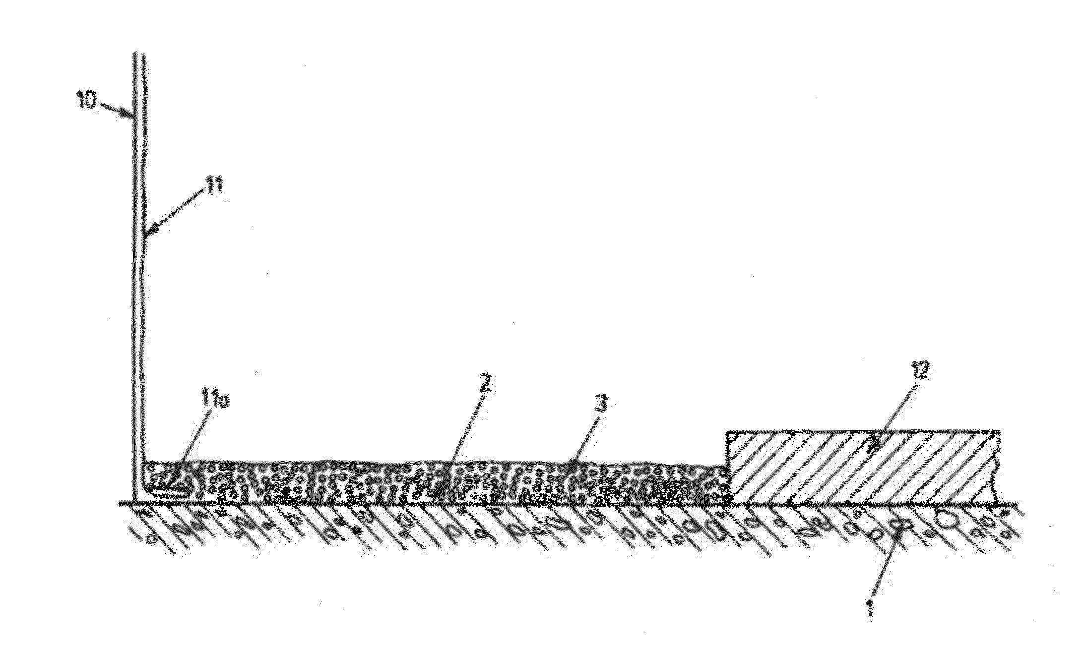
Image

Examples
example 1
Preparation and Application of a Shielding Layer (Initial Recipe)
[0280]The composition of the present invention was developed and tested as a prototype of a new shielding material and shielding technology in the local University Hospital of the University of Stavanger.
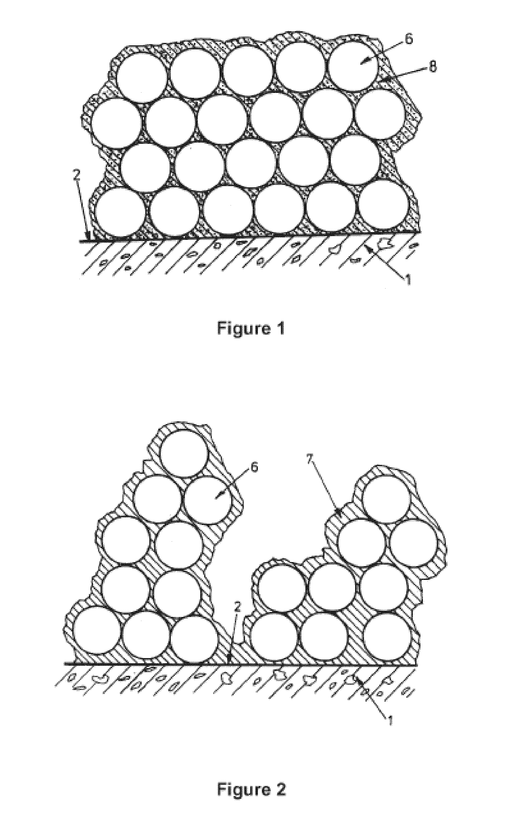
[0281]The composition has successfully been installed as a four component based flooring material for isolation of radiation. The composition comprises lead particles (similar to commercially available lead shots), epoxy resin, filler material and sand according to the weight % ratio indicated in table 1. The mix below was the best performing mix of the ones tried out.
Weight (kg)VolumeLead particles (Ø 2 mm)64.5Epoxy0.31.5Filler material (0.21grained inert material (0.1-1 mm)0.421.5Total6.92 kg / liter
[0282]Mixing of the resin and a hardener material was carried out with a powerful drill to which a whisk was attached. In a further step lead shots and particulate materials and filler-substances were added to the mixture a...
example 2
Testing the Initial Shielding Layers of the Invention
[0283]Comparative measurements were carried out with the composition of the present invention containing different ratios of the main ingredients. The present inventors have made several test slabs of 40×40 cm size and different thickness and compositions with different ingredient ratios were poured into the slabs to test the quality and radiation attenuating performance of the thus created sample flooring.
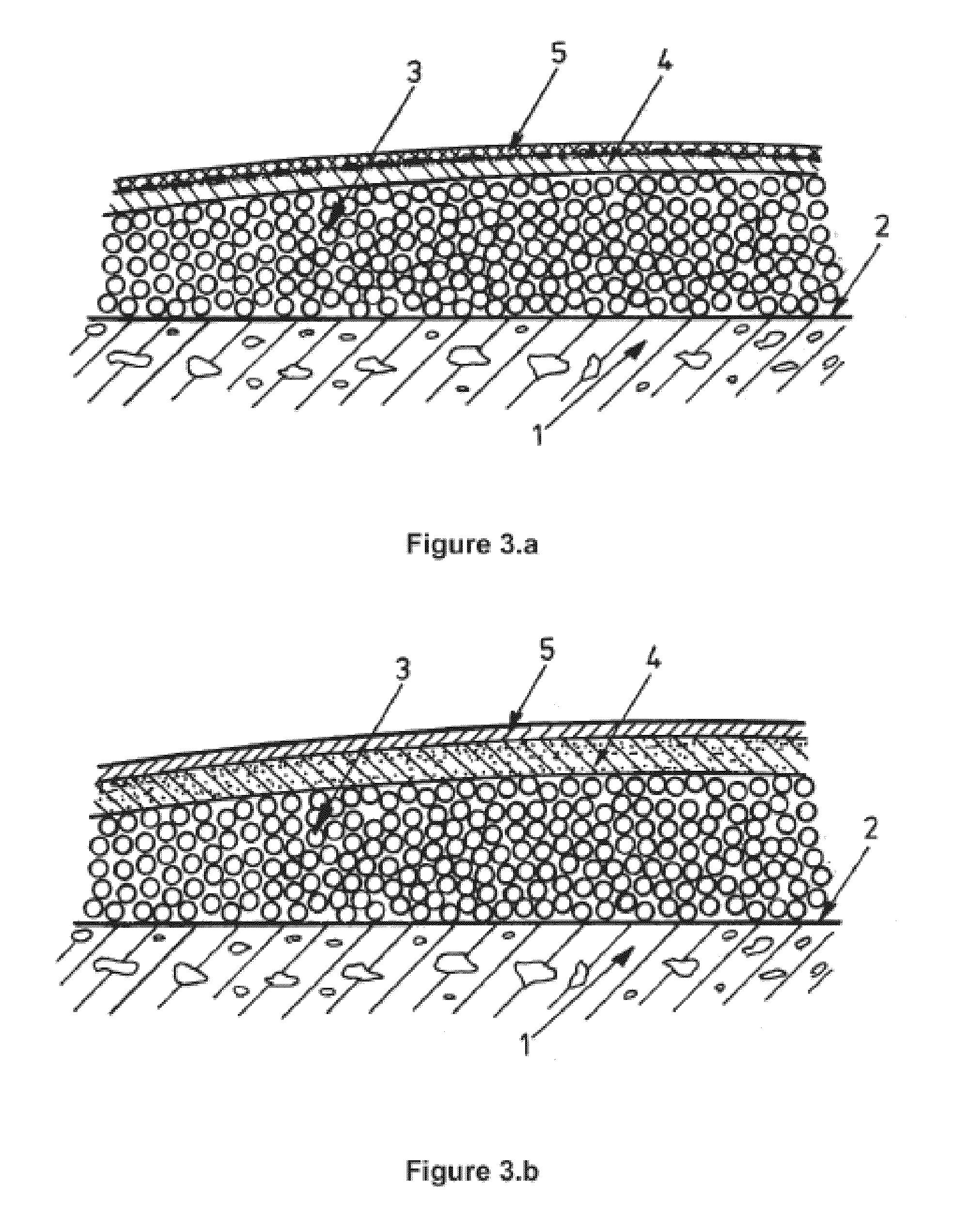
[0284]Four samples were tested. Sample I and II were a mix of lead shots and epoxy. Sample III and IV were a mix of lead shots, epoxy, sand and filler material, here in this example finely crushed sand. Compositional data of Samples I-IV are listed below, in Table 2, together with layer thickness data.
Amount of component in volume partsleadthicknessshotsepoxy bindersandfiller(mm)Sample I31——5Sample II31——7.5-8Sample III310.40.45Sample4.51.411.55IV
[0285]The mix of Sample I and II did not have a proper internal bonding and had poo...
example 3
Preparing a Flooring in the Hospital of Stavanger
[0289]For laying the final floor we decided to go for mix 4 and with a thickness for 6 mm. To be on the safe side we increased the floor to 7 mm. The whole floor was casted in one operation to avoid casting extension lines. The work took about 6 hours for a 40 m2 floor. Post inspection based on visual measurement and calculations of used material suggest that the floor is between 6 and 7 mm. Test measurements were done as described below. The day after a thin layer of epoxy was rolled (painted) on and sprinkled with dry sand. This was to ensure proper adhesion to the anti static vinyl layer that was glued on as the top layer.
[0290]The shielding was sufficient to meet governmental requirements, met the requirements of the CT scanner provider, was sufficiently smooth and thin so as to avoid jolts and bumps of wheeled vehicles when entering the room.
PUM
| Property | Measurement | Unit |
|---|---|---|
| grain size | aaaaa | aaaaa |
| particle size | aaaaa | aaaaa |
| particle size | aaaaa | aaaaa |
Abstract
Description
Claims
Application Information