Optical film, polarizing plate, and method for producing optical film

a technology of optical film and polarizing plate, which is applied in the direction of polarizing elements, instruments, nuclear engineering, etc., can solve problems such as coloration at the time of use, and achieve the effects of superior performance, high contrast and reduced thickness

Active Publication Date: 2015-10-01
FUJIFILM CORP
View PDF4 Cites 61 Cited by
  • Summary
  • Abstract
  • Description
  • Claims
  • Application Information

AI Technical Summary

Benefits of technology

[0044]According to the present invention, an optical film having a novel configuration, which can be used as a phase difference plate, is provided. The optical film of the present invention is configured such that the film is a broadband phase difference plate, and can...

Problems solved by technology

A phase difference plate is usually difficult to be prepared as a phase difference plate giving the same effects as the light at any wavelength with respect to white light with a synthetic wave having mixed rays in a visible light region, and thus, for example, the phase differe...

Method used


Image

  • Optical film, polarizing plate, and method for producing optical film
  • Optical film, polarizing plate, and method for producing optical film
  • Optical film, polarizing plate, and method for producing optical film

Examples


example 1-1

[0240]

[0241]A commercially available triacetyl cellulose film “Z-TAC” (manufactured by Fujifilm Corporation) was used as a support. The triacetyl cellulose film was allowed to pass through dielectric heating roll supports at a temperature adjusted to 60° C. to elevate the temperature of the film surface of the support to 40° C., and then an alkali solution having the composition shown below was applied onto one surface of the film in a coating amount of 14 ml / m2, using a bar coater. Thereafter, the support was heated to 110° C. and transported below a steam type far infrared ray heater manufactured by Noritake Co., Ltd. for 10 seconds. Subsequently, using a bar coater in the same manner as describe above, pure water was applied onto the surface which had been coated with the alkali solution in an amount of 3 ml / m2. Then, washing with water using a fountain coater and then dehydration using an air knife were repeated three times, respectively. Subsequently, the film was transported i...

example 1-2

[0255]

[0256]The support surface of a cellulose triacetate film TD8OUL (manufactured by Fujifilm Corporation) was subjected to an alkali saponification treatment. Specifically, the support was immersed in a 1.5 N aqueous sodium hydroxide solution at 55° C. for 2 minutes, washed in a water bath at room temperature, and neutralized with 0.1 N sulfuric acid at 30° C. Then, the support was washed again in a water bath at room temperature and further dried with hot air at 100° C.

[0257]A roll-shaped polyvinyl alcohol film having a thickness of 80 μm was continuously stretched in the MD direction to a length 5 times the original length in an aqueous iodine solution by the same procedure as in Example 1-1, and dried to form a polarizing film having a thickness of 20 μm.

[0258]The side of the positive C-plate of the optical film 1 was bonded to one side of the polarizing film prepared above, and the cellulose triacetate film which had been subjected to an alkali saponification treatment was bo...

example 2

[0259]

[0260]The following coating liquid 2 for a positive A-plate was prepared.

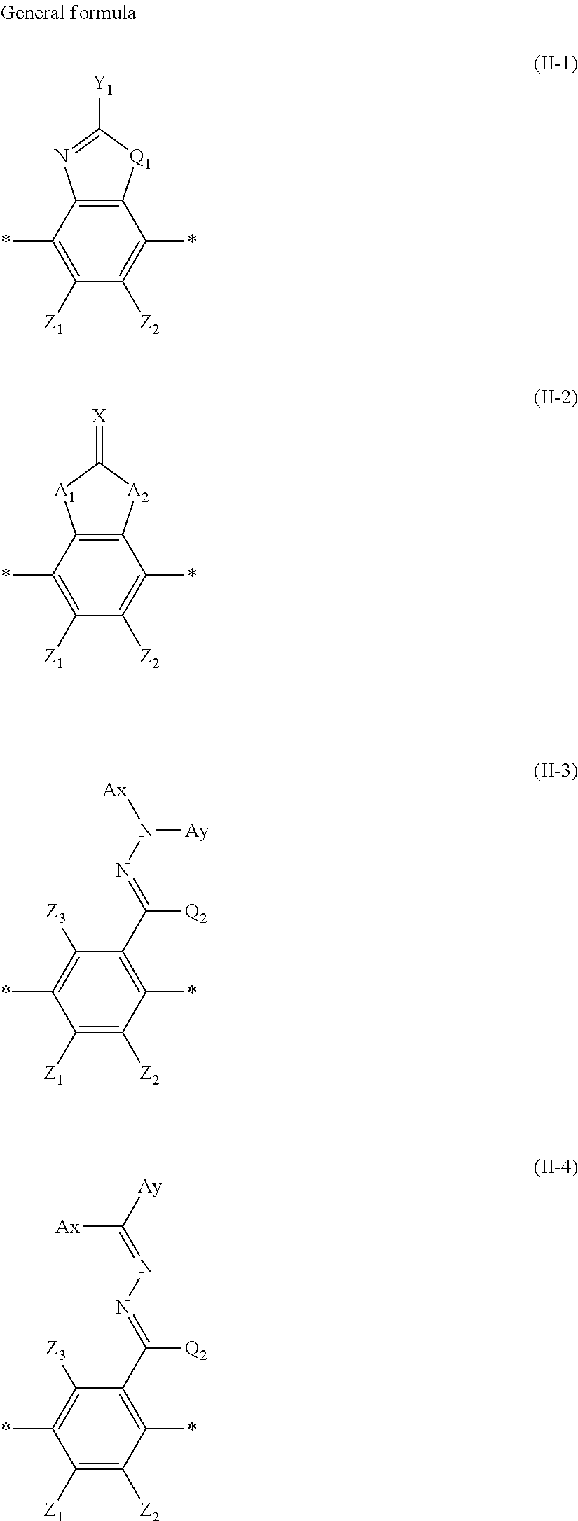
Composition of coating liquid 2 for forming positive A-plate A-0Reverse wavelength dispersion liquid crystal compound R-2100 parts by massPhotopolymerization initiator (Irgacure 819, manufactured by BASF Japan Ltd.)3.0 parts by massFluorine-containing compound A0.8 parts by massCross-linkable polymer O-20.3 parts by massChloroform588 parts by massReverse wavelength dispersion liquid crystal compound R-2: Specific Example II-2-2

Cross-linkable polymer: O-2

[0261]For the cross-linkable polymer O-2, Tg =10° C.

[0262]According to the same procedure as in Example 1-1, the triacetyl cellulose film having the alignment film 1 on the surface was prepared and the alignment film 1 was subjected to a rubbing treatment. The coating liquid 2 for forming a positive A-plate A-0 was applied onto the rubbing-treated surface, using a bar coater, heated and aged at a film surface temperature of 150° C. for 60 seconds, and then...


PUM

PropertyMeasurementUnit
Angleaaaaaaaaaa
Angleaaaaaaaaaa
Percent by massaaaaaaaaaa

Abstract

An optical film of the present invention includes a positive A-plate and a positive C-plate, in which the Re(450), Re(550), and Re(650) of the positive A-plate satisfy the relationship of Re(450)≦Re(550)≦Re(650), the positive A-plate is formed of a cured product of a composition including the liquid crystal compound A, and the positive C-plate is formed of a cured product of a composition including the liquid crystal compound C.

Description

CROSS-REFERENCE TO RELATED APPLICATIONS[0001]The present application claims priority under 35 U S.C. §119 to Japanese Patent Application No. 2014-071861, filed on Mar. 31, 2014, Japanese Patent Application No. 2014-140956, filed on Jul. 8, 2014, and Japanese Patent Application No. 2014-177467, filed on Sep. 1, 2014. Each of the above applications is hereby expressly incorporated by reference, in its entirety, into the present application.BACKGROUND OF THE INVENTION[0002]1. Field of the Invention[0003]The present invention relates to an optical film, a polarizing plate, and a method for producing the optical film.[0004]2. Description of the Related Art[0005]An optical film having a function as a phase difference plate has frequently been used in a liquid crystal display apparatus, and for example, a λ / 4 phase difference plate in a form in combination with a linearly polarizing plate has often been used as a circularly polarizing plate. In order to attain a high contrast in the inclin...

Claims


Application Information

Patent Timeline
IPC IPC(8): G02B5/30C09K19/54C09K19/34C09K19/20G02B1/11G02B1/12
CPCG02B5/3016G02B5/3083G02B1/11C09K19/542C09K19/3497C09K19/2007C09K19/3491G02B1/12C09K19/2014C09K19/348C09K19/3486C09K19/3494C09K19/601C09K2019/0448C09K2019/3077C09K2019/548
Inventor TAKASAGO, RIEMATSUYAMA, HIROSHIISHIGURO, MAKOTOMORISHIMA, SHINICHI
Owner FUJIFILM CORP
Why Eureka
Try Eureka