

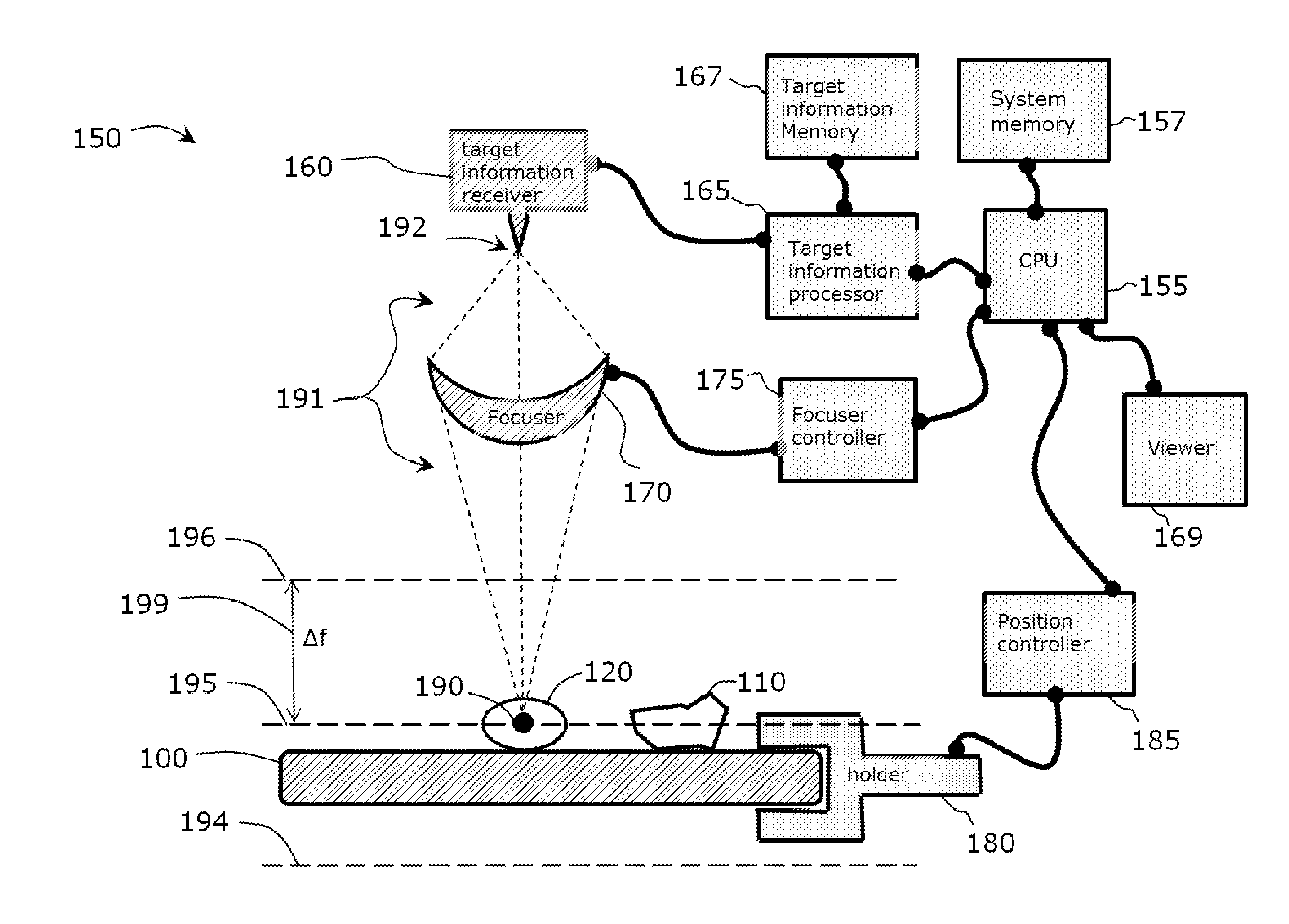
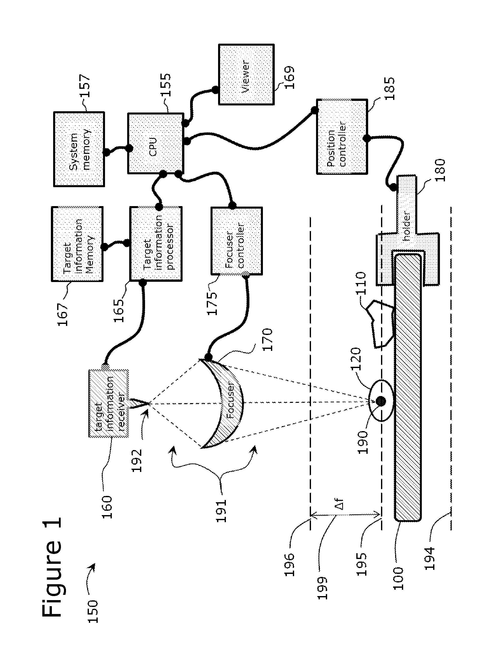
Use of Microparticle Additives to Simultaneously Enable Artifact-Free Image Registration, Auto-Focusing, and Chromatic Aberration Correction in Microscopy
a technology of microparticles and additives, applied in image enhancement, instruments, optical elements, etc., can solve the problems of unacceptable optical focal plane variations from region to region, image signals may impinge on too few detector pixels to capture fully the image details, and the auto-focusing can be particularly challenging
- Summary
- Abstract
- Description
- Claims
- Application Information
AI Technical Summary
Benefits of technology
Problems solved by technology
Method used
Image

Examples
example 1
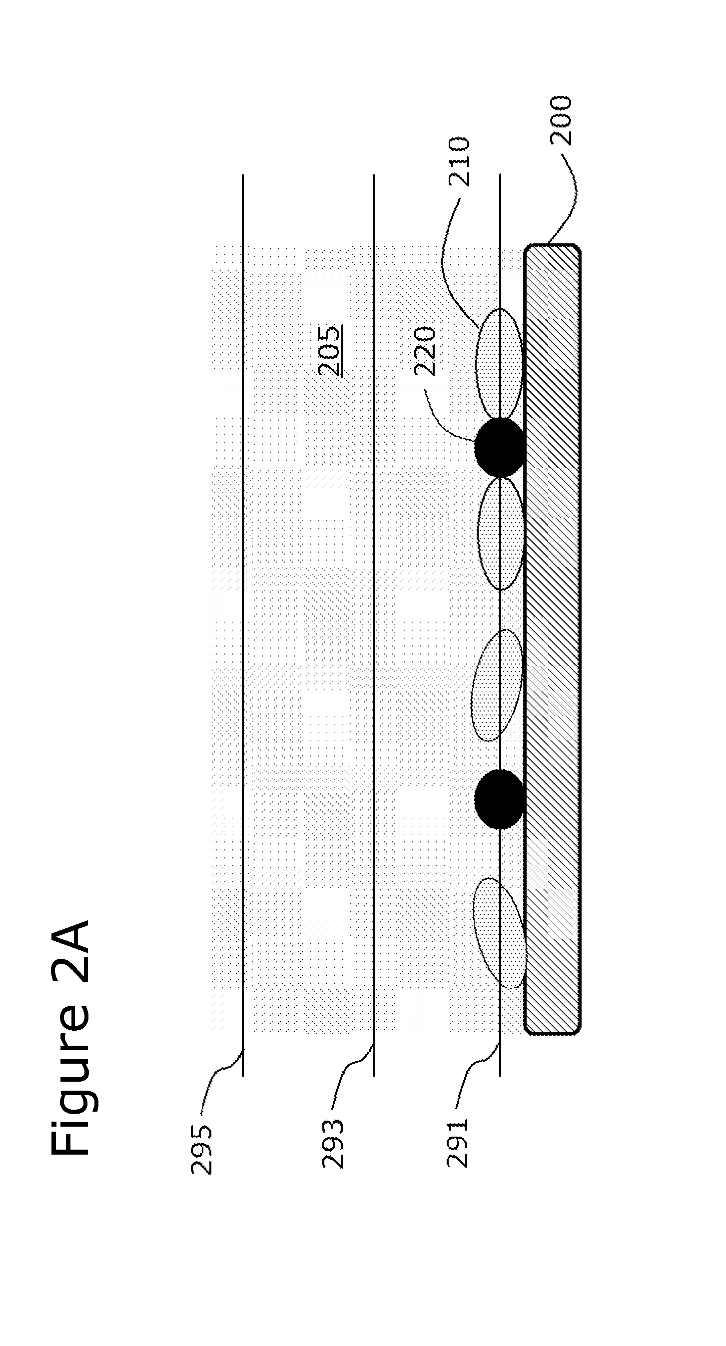
[0111]Glass microbeads, approximately 10-30 microns in size, having a density of about 2.5 g / mL and a refractive index of about 1.5, were mixed into a solution containing fluorescently-stained and non-stained cells. The solution was deposited onto a surface and imaged by brightfield optical microscopy at low-magnification (about 1.3× magnification). Standard auto-focusing algorithms were unable to focus on the low-contrast cells under standard bright-field imaging conditions without the microparticles present. The addition of the microparticles into the solution enabled standard auto-focusing algorithms to achieve focus at the correct focal plane, namely the plane contained the cells. At the same time, these high-contrast microparticles were less prone to movement than low-density microparticles, which enabled them to act as registration markers (fiduciary points) to register multiple images together in bright-field imaging mode.
[0112]Additional Experiments
[0113]A series of imaging ...
PUM
 Abstract
Description
Claims
Application Information