Heat Recovery Method and Apparatus

a heat recovery and heat recovery technology, applied in the field of heat recovery methods and apparatuses, can solve the problems of high implementation costs, increase pollutants, waste of energy, etc., and achieve the effects of improving the thermal efficiency of water heaters, reducing the temperature of flue gas, and high efficiency

Inactive Publication Date: 2015-10-29
IDALEX TECH INC
View PDF12 Cites 13 Cited by
  • Summary
  • Abstract
  • Description
  • Claims
  • Application Information

AI Technical Summary

Benefits of technology

[0020]The present invention improves the thermal efficiency of a water heater (or similar heating equipment) whenever the equipment is in operation, and not just when cold water is available to cool flue gases. Providing high efficiency is accomplished by reducing the flue gas temperature below its dew point temperature or lowering its enthalpy to near the outdoor air temperature enthalpy whenever in operation. This is accomplished by a second stage Heat and Mass Exchanger (HMX) that heats and humidifies input combustion air while cooling and condensing flue gas. A first stage heat exchanger or condensing hot water heater initiates the flue gas cooling and / or condensing process. The condensing starts at a much higher temperature than previous water heaters due to the added humidity in the combustion air and thus a higher dew point temperature of the flue gas.

Problems solved by technology

Most industrial processes use large quantities of fuel and electricity that ultimately produce heat, much of which is wasted either to the atmosphere or to water.
However, in other applications it may increase pollutants (e.g., preheating combustion air increases combustion temperatures which can increase NOx) and maintenance.
Extreme values of any of these may dictate the use of special materials and design, resulting in high implementation costs.
This list identifies process input and output characteristics that can help give a relative sense of possible energy savings from waste-heat recovery.The greater the temperature, flow rate and moisture content, the greater the quantity of heat in the stream.The proximity of waste-heat to possible processes that could uses this heat influences total energy savings, due to heat loss in fluid transit from the source, and the energy required to move the fluid.Latent heat from the condensation of moisture in exhaust gas can be significant; however condensation is often undesirable due to low condensing temperatures and the potential for corrosion down-stream of the heat-recovery device.
Most of the energy savings will affect fuel consumption, however, electrical heating of ancillary equipment may also be affected.
Preheaters for hot water heating systems are not per se new.
The drawback to the CWH is that often hot water use is sporadic so that small amounts of cold water are brought in and the burners are on for a much longer time than the water coming in.
This means there is often little to no incoming water to preheat the hot exhaust gas and thus little efficiency gain.
However, in such a water heater the hot exhaust gas is cooled with cold or cool water that is not always available and may discharge hot flue gas from the heat exchanger with insufficient cooling for condensing preventing high efficiency.
The water heaters of the conventional type described above often have less than ideal levels of combustion efficiency and undesirably high levels of emitted pollutants such as Nitrogen Oxide and Carbon Monoxide.

Method used


Image

  • Heat Recovery Method and Apparatus
  • Heat Recovery Method and Apparatus
  • Heat Recovery Method and Apparatus

Examples


Embodiment Construction

Reference Number List

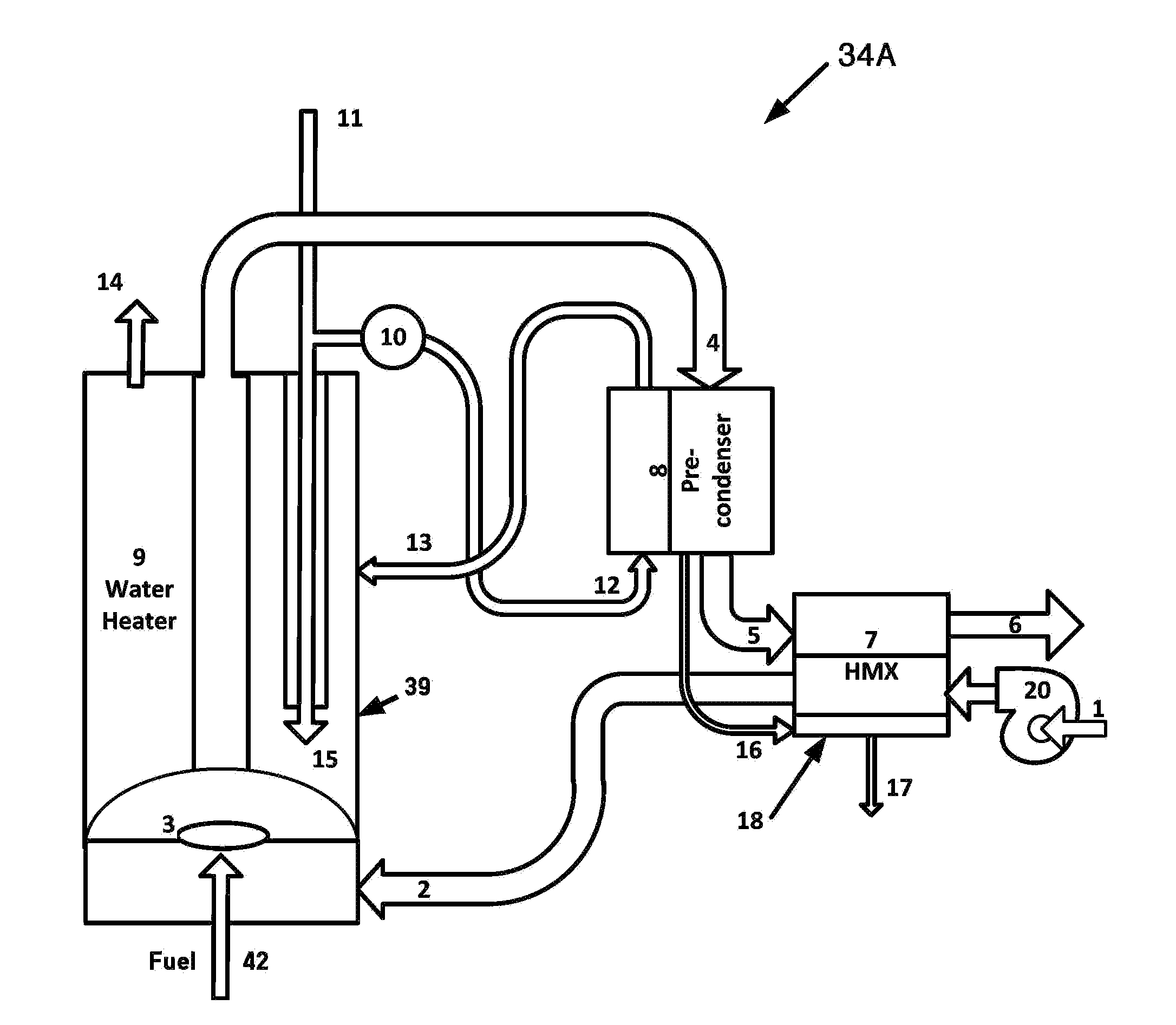
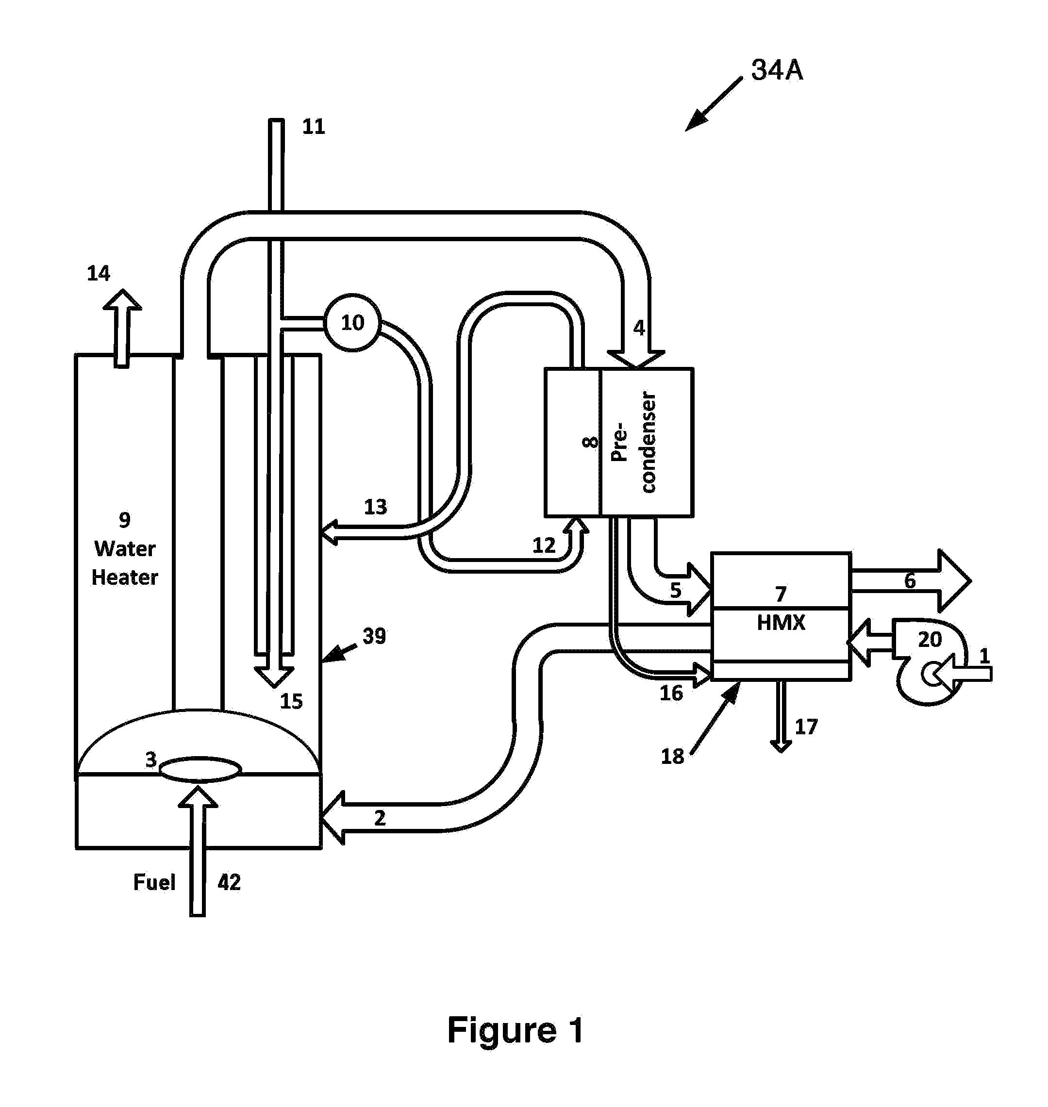
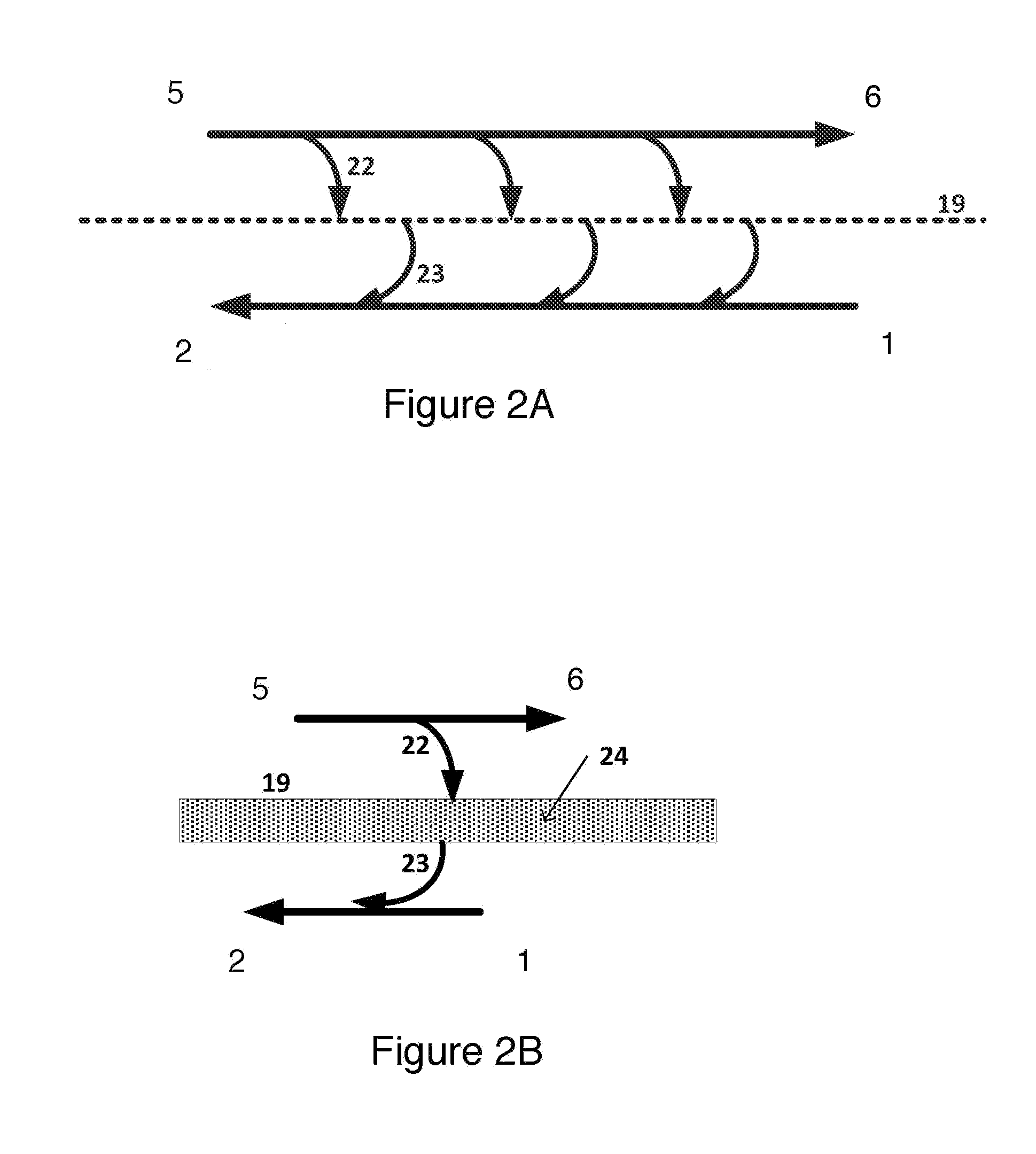
[0061]1, 301 Input Combustion Air[0062]2, 302 Saturated Combustion Air[0063]3, 303 Combustor[0064]4, 304 Hot Flue Gas[0065]5, 305 Precooled (Warm) Flue Gas[0066]6, 306 Flue Gas Out (Cool)[0067]7, 307 Heat and Mass Exchanger HMX[0068]8, 308 Pre-cooler[0069]9 Water Heater[0070]10 Pump[0071]11 Cold Water In[0072]12 Cooling Water[0073]13 Heated Water[0074]14 Hot Water Out[0075]15 Cool Water to Tank[0076]16 Liquid (Condensate)[0077]17 Drain Water[0078]18 Trough[0079]19 Membrane,s (Plates)[0080]20 Fan[0081]22 Heat[0082]23 Evaporated Water[0083]24 Membrane Water[0084]25 Trough End Cap[0085]26 Dry (condensing) Side of Membrane[0086]27 Trough Overflow Perforations[0087]28 Channel Guide[0088]29 Impervious Coating[0089]30 Wet (evaporating) Side of Membrane[0090]32 Condensing Water Heater[0091]34 HMX Humid Air Recovery System[0092]35 Flue Gas Coil[0093]36 Tank Water[0094]37 Flue Gas Channels[0095]38 Combustion Air Channels[0096]39 Tank of Hot Water Heater 9[0097]40 Non-cond...


PUM


Abstract

A hot water heater or similar heating device includes equipment for pre-cooling hot flue gas while preheating water for the water heater. It further includes a heat and mass exchanger for transferring heat and water from the pre-cooled flue gas to combustion air for the hot water heater. The pre-cooler may comprise a separate device or may be incorporated as part of a condensing water heater. The heat and mass exchanger may use membranes having condensing sides and evaporating sides, which allow water to pass from the condensing sides to the evaporating sides. It may further comprise troughs for wetting the membranes.

Description

BACKGROUND OF THE INVENTION[0001]1. Field of the Invention[0002]The present invention relates to methods and apparatus for improving the efficiency of systems such as gas hot water heaters by a process of humid flue gas heat recovery.[0003]2. Discussion of Related Art[0004]Most industrial processes use large quantities of fuel and electricity that ultimately produce heat, much of which is wasted either to the atmosphere or to water. A variety of methods and equipment have been developed to reuse some of this waste heat. This may save up to approximately 20 percent of a facility's annual fuel bill and, in some instances, reduce pollution emissions and plant maintenance. However, in other applications it may increase pollutants (e.g., preheating combustion air increases combustion temperatures which can increase NOx) and maintenance.[0005]Waste heat's usefulness is determined by its temperature; the higher the temperature the higher the quality or value. Most waste-heat-recovery devic...

Claims


Application Information

Patent Timeline
Patent Type & Authority Applications(United States)
IPC IPC(8): F24H8/00F24H1/18
CPCF24H8/003F24H8/006F24H1/186F28D21/0015Y02B30/00
Inventor GILLAN, LELAND E.MAISOTSENKO, VALERIYGILLAN, ALAN
Owner IDALEX TECH INC
Why Eureka
Try Eureka