Method of manufacture of particles with controlled dimensions

a technology of controlled dimensions and manufacturing methods, applied in the direction of magnetic bodies, natural mineral layered products, synthetic resin layered products, etc., can solve the problems of reducing the efficiency of the reflective surface, incomplete or inadequate production of thin flakes, physical fragility of the master hologram, etc., to reduce the risk of damage to the surface structure, reduce the risk of local overheating attack or stress, and achieve the effect of realizing production speed

Active Publication Date: 2015-11-26
SZUSCIK MACHNICKI ANDREW HENRY
View PDF2 Cites 52 Cited by
  • Summary
  • Abstract
  • Description
  • Claims
  • Application Information

AI Technical Summary

Benefits of technology

[0054]The above resins are curable at relatively low temperatures (less than 50° C.) or even ambient temperatures while operating at realistic production speed and therefore reduce the risk of damage to the surface structure by avoiding local overheating attack or stress. These resins can also be used as

Problems solved by technology

The master hologram is physically delicate and is not used directly to mass-reproduce copies.
However, there remains a problem with this prior art in that the stresses associated with the deposition and stripping process result in stress-cracking and random fracture of the deposited material, resulting in incomplete or inadequate production of thin flakes which replicate the desired shape of the frame embossed in the carrier sheet.
These peripheral frame impressions give rise to specious reflection and/or diffraction of light from the flake surface and reduce the efficiency of the refle

Method used


Image

  • Method of manufacture of particles with controlled dimensions
  • Method of manufacture of particles with controlled dimensions
  • Method of manufacture of particles with controlled dimensions

Examples


example 1

[0126]A polymer composition comprising polyethylene terephthalate was coextruded with a copolyester comprising terephthalic acid / isophthalic acid / ethylene glycol (82 / 18 / 100), cast onto a cooled rotating drum and stretched in the direction of extrusion to approximately 3 times its original dimensions at a temperature of approximately 90° C. The film was then passed through an inter-draw coater where a release coating comprising partially-esterified styrene maleic anhydride was applied as an aqueous solution at a concentration of 7% solids to one side of the film by a reverse roll direct coater. The coater speed was between 7 and 11 m·min−1 and the line-speed was between 10 and 15 m·min−1 The film was passed into a stenter oven at a temperature of 100° C. where the film was stretched in the sideways direction to approximately 3 times its original dimensions. The biaxially-stretched film was heat-set at a temperature of about 230° C. by conventional means. The total thickness of the co...


PUM

PropertyMeasurementUnit
Lengthaaaaaaaaaa
Nanoscale particle sizeaaaaaaaaaa

Abstract

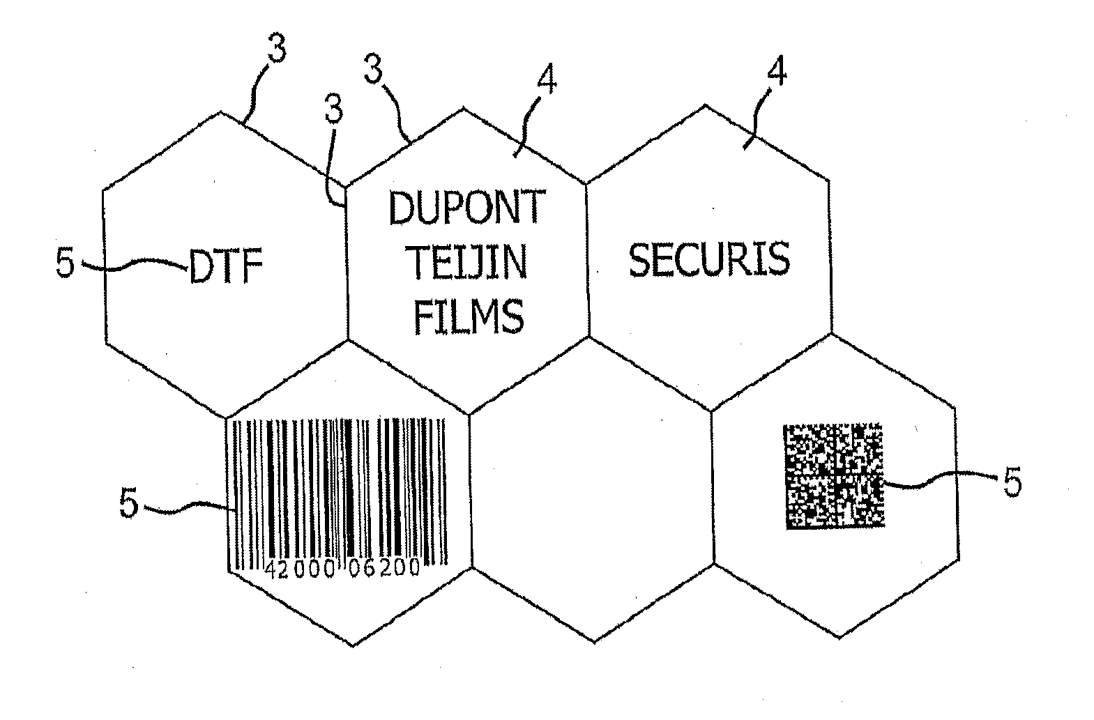
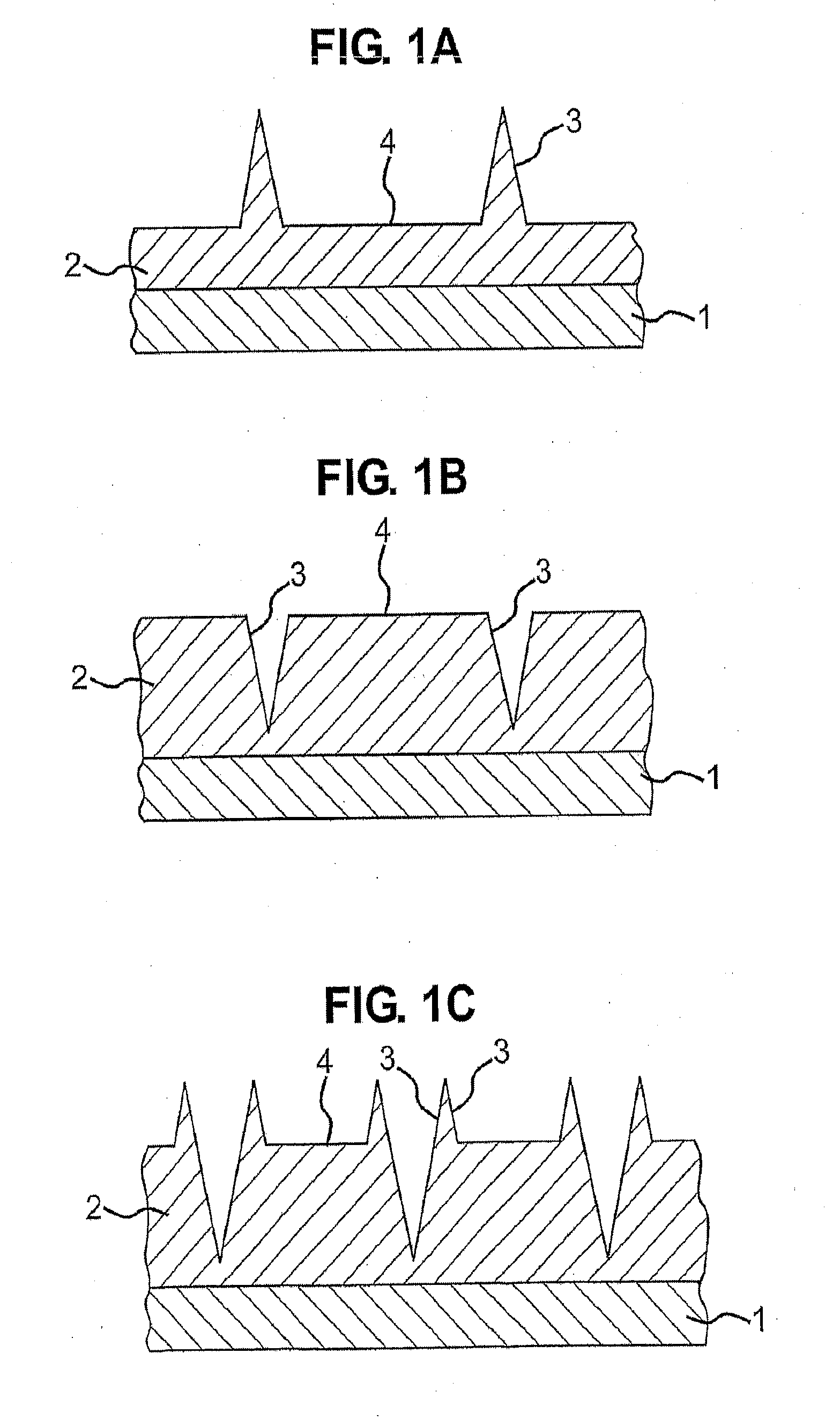
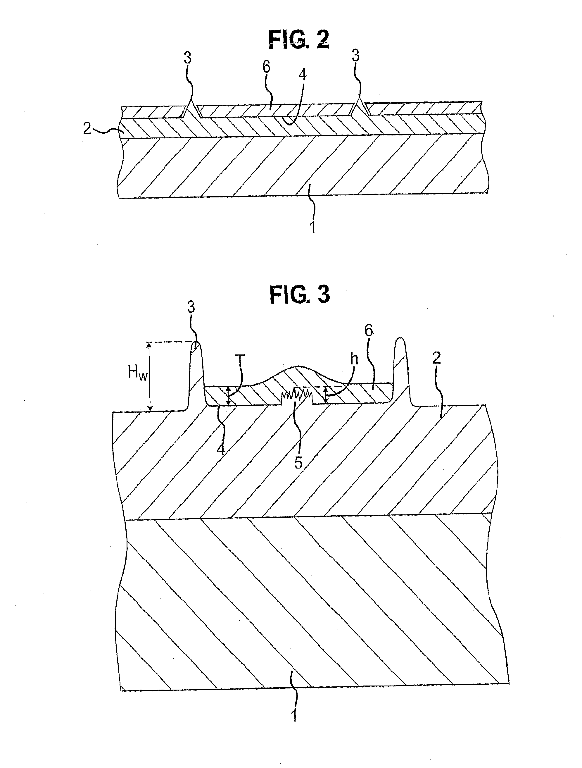
A process for the preparation of particles with controlled dimensions comprising the steps of: (i) providing a laminar substrate having a patterned surface comprising a micro-relief repeat pattern comprising one or more discrete cells, each cell consisting of a floor portion and walls having a height (HW); (ii) depositing organic or inorganic material onto the patterned surface and into the cells to provide a thickness (T) of the deposited material wherein T≦HW (iii) stripping the deposited organic or inorganic material from the surface of the substrate; and (iv) collecting the particles formed from said organic or inorganic material; and a composition obtainable from said process comprising a plurality of particles (P), wherein the number (n) of particles in said composition is at least 10, wherein said particles (P) are platelets exhibiting a planar geometry which is circular or which is made up of a number (x) of planar (y)-sided polygon(s), wherein x is from 1 to 20 and y is at least 3 wherein if x is greater than 1 then said planar (y)-sided polygons are fused along one or more sides thereof, wherein the width (WP) of the platelets (P) at their widest point is no more than about 250 pm and the thickness of the platelets (P) is in the range of 10 nm to 50 nm.

Description

INCORPORATION BY REFERENCE TO ANY PRIORITY APPLICATIONS[0001]Any and all applications for which a foreign or domestic priority claim is identified in the Application Data Sheet as filed with the present application are hereby incorporated by reference under 37 CFR 1.57.BACKGROUND[0002]1. Field[0003]The present invention relates to the manufacture of particles with controlled dimensions, particularly those having at least one embossed surface; a composition comprising such particles; and the use of such particles in inter alia paints, printing inks, spray paints, cosmetic products, high surface area ceramics or ceramic bodies, coloured plastics and optical elements or as an anti-counterfeit or security pigment.[0004]2. Description of the Related Art[0005]The preparation of embossed surfaces is well-known in the art, including the preparation of surfaces with a diffraction pattern or grating. A diffraction grating is formed when closely and regularly spaced grooves (typically 5,000 to...

Claims


Application Information

Patent Timeline
IPC IPC(8): C09C1/64B22F1/00C22C21/00B22F1/068
CPCC09C1/64C22C21/00Y10T428/2982Y10T428/12Y10T428/12993B22F1/0055B22F9/02B22F2998/10C01P2004/52C01P2004/61C09C1/0015C09C1/0018C09C2200/1004C09C2200/1054C09C2200/1087C09C2200/301C09C2210/40B22F1/0551B22F1/0553B22F1/068B22F3/115B22F7/04
Inventor SZUSCIK-MACHNICKI, ANDREW HENRYDAWES, MARK EDWARD
Owner SZUSCIK MACHNICKI ANDREW HENRY
Why Eureka
Try Eureka