Trim method for high voltage drivers

Active Publication Date: 2015-12-31
SCHIE DAVID +2
View PDF0 Cites 6 Cited by
  • Summary
  • Abstract
  • Description
  • Claims
  • Application Information

AI Technical Summary

Benefits of technology

[0011]Methods and circuits are provided to create small, power minimizing, multi-channel high-voltage drivers for micro-electromechanical systems (MEMS). A resistor calibration circuit is introduced to allow on-chip resistor dividers to be calibrated against a single precision high-voltage resistor divider, eliminating the cost and printed circuit board real estate associated with multiple resistor dividers connected to each

Problems solved by technology

At these sizes, the standard constructs of classical physics are not always useful.
Unfortunately, high valued resistors of high precision and with tight drift and temperature specifications and high initial accuracy are very expensive and difficult to source.
Furthermore, arraying large numbers of high valued resistors across a printed circuit board creates high impedance nodes which are sensitive to noise coupling and leakage and uses a lot of space.
The result is that most MEMS drivers have poor accuracy, “glitching problems,” poor power characteristics, and are often much larger than the MEMS devices they are trying to drive.
In general high voltage integrated circuits either use internal resistors, in which case their relative accuracy is poor, especially over the drift of the process, or high voltage integrated

Method used


Image

  • Trim method for high voltage drivers
  • Trim method for high voltage drivers
  • Trim method for high voltage drivers

Examples


Example

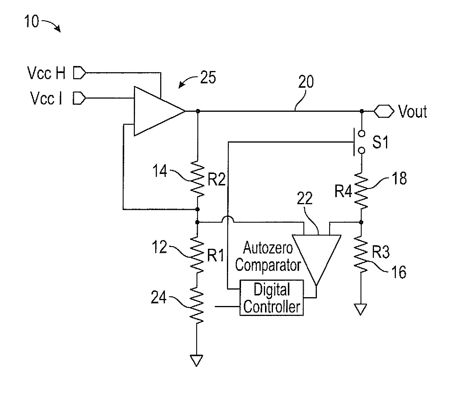
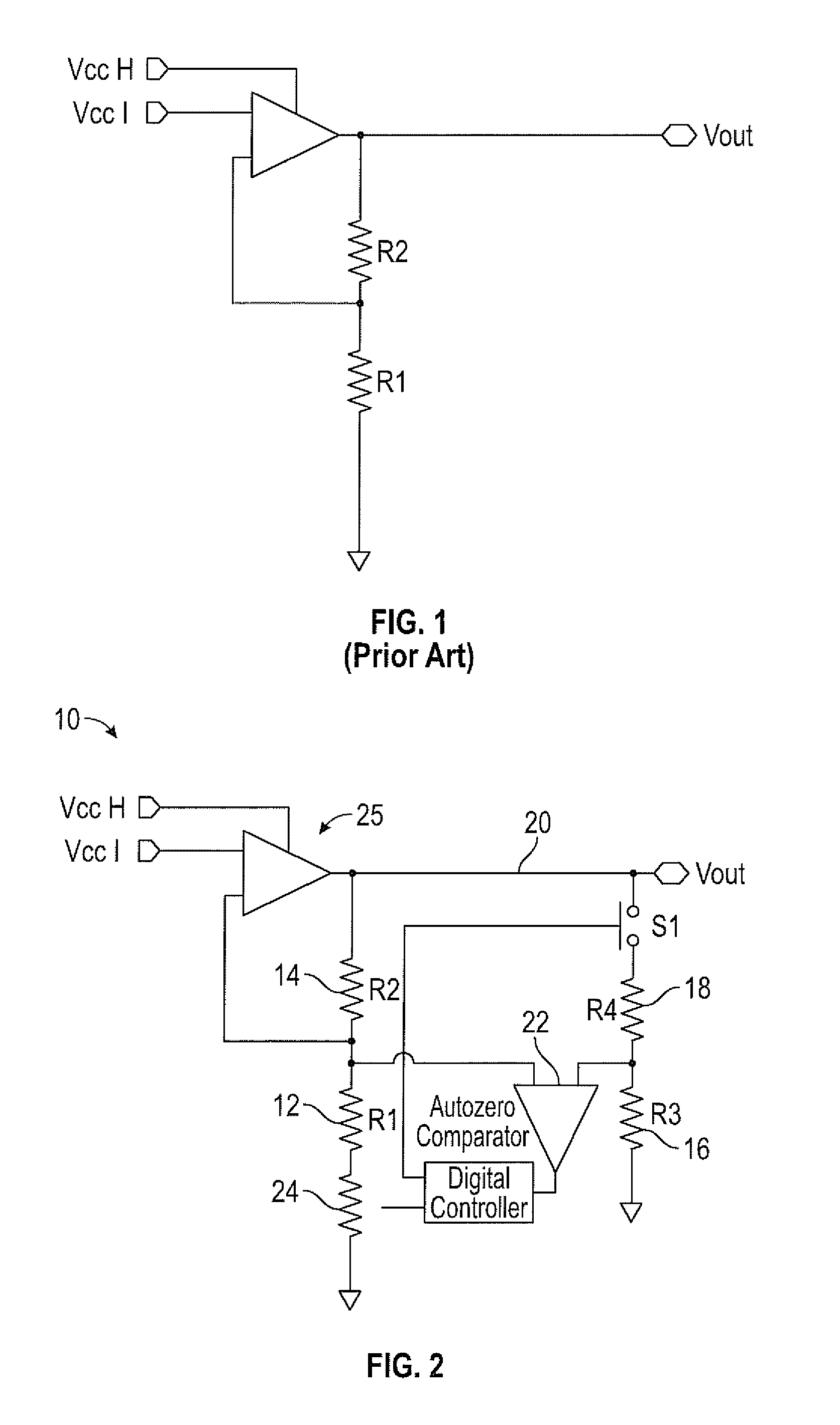
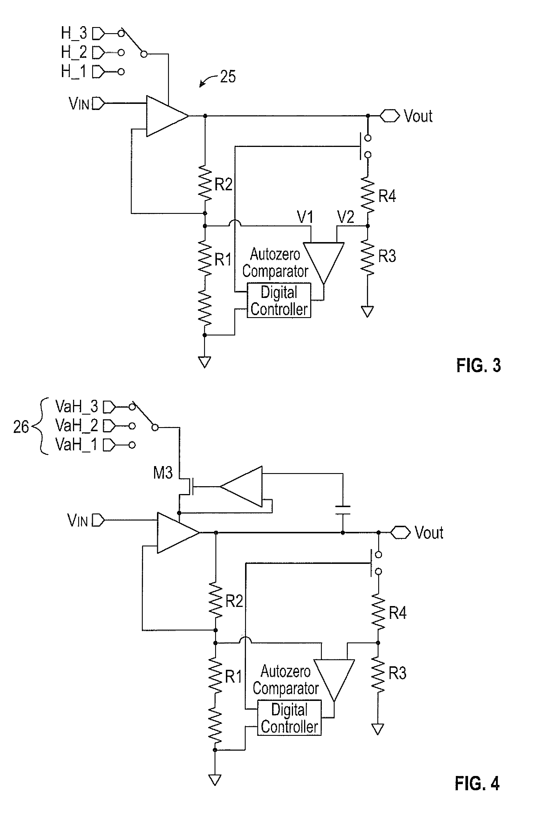
[0021]The present invention has utility as improved methods and circuits to create small, power minimizing, multi-channel high voltage drivers for micro-electromechanical systems (MEMS). A resistor calibration circuit is introduced to allow on chip resistor dividers to be calibrated against a single, low drift, precision, high-voltage resistor divider, eliminating the cost and required printed circuit board real estate associated with multiple resistor dividers connected to each channel. Additionally, a multiple-power rail circuit configuration is taught to reduce power to the overall system by producing several rails generated by a boost converter and / or a capacitive charge pump, where the voltage output of the rails is produced to group rails of lesser voltage requirement rather than connecting all channels to the same high voltage rail on a dynamic basis.

[0022]In embodiments of the invention, an integrated circuit device is introduced where two or more high voltage outputs are co...


PUM


Abstract

Methods and circuits are provided to create small, power minimizing, multi-channel high voltage drivers for micro-electromechanical systems (MEMS). A resistor calibration circuit is introduced to allow on chip resistor dividers to be calibrated against a single precision high voltage resistor divider, eliminating the cost and printed circuit board real estate associated with multiple resistor dividers connected to each channel. Additionally, a multiple-power rail configuration is provided to reduce power to the overall system by producing several rails generated by a boost converter or a capacitive charge pump, where the voltage output of the rails is produced to group rails of lesser voltage requirement rather than connecting all channels to the same high voltage rail on a dynamic basis.

Description

CROSS-REFERENCE TO RELATED APPLICATION[0001]This application claims priority of U.S. Provisional Patent Application Ser. No. 61 / 786,310 filed Mar. 15, 2013, which is incorporated herein by referenceFIELD OF THE INVENTION[0002]The present invention in general relates to electronic components and in particular to methods and circuits to create small, power minimizing, multi-channel high voltage drivers for micro-electromechanical systems (MEMS).BACKGROUND OF THE INVENTION[0003]Microelectromechanical systems (MEMS) is the technology of very small devices, that merge at the nano-scale into nanoelectromechanical systems (NEMS) and nanotechnology. MEMS are made up of components between 1 to 100 micrometers in size (i.e. 0.001 to 0.1 mm), and MEMS devices generally range in size from 20 micrometers (20 millionths of a meter) to a few millimeters (i.e. 0.02 to >1.0 mm). MEMS usually consist of a central unit that processes data (the microprocessor) and several components that interact wi...

Claims


Application Information

Patent Timeline
IPC IPC(8): H03K19/00H03K17/16H02M3/07H03K5/24
CPCH03K19/0005G05F3/02
Inventor SCHIE, DAVIDWARD, MIKESPADY, DAVID
Owner SCHIE DAVID
Why Eureka
Try Eureka