Medical successive magnetic pulse generation device

Inactive Publication Date: 2016-06-02
IFG +2
View PDF3 Cites 27 Cited by
  • Summary
  • Abstract
  • Description
  • Claims
  • Application Information

AI Technical Summary

Benefits of technology

[0037]According to the present invention, the problem of an increase in charge current which is a major obstacle to successive generation of strong magnetic pulses for peripheral nerve stimulation from the medical magnetic pulse generation device can be solved without using a high-capacity resistor having large power consumption, a heavy, bulky, and large-sized step-up transformer, a charging circuit configured as a multi-channel type, etc., and it is possible to achieve size and weight reduction and power saving of the device. Due to the size reduction and power saving, the

Problems solved by technology

The low-frequency therapeutic device can cause muscle contraction with low electric power, and thus the size of the device can be very small.
However, it takes time and effort to attach the electrode to the skin, and in the case of causing great muscle contraction, there is a p

Method used


Image

  • Medical successive magnetic pulse generation device
  • Medical successive magnetic pulse generation device
  • Medical successive magnetic pulse generation device

Examples


Example

Example 1

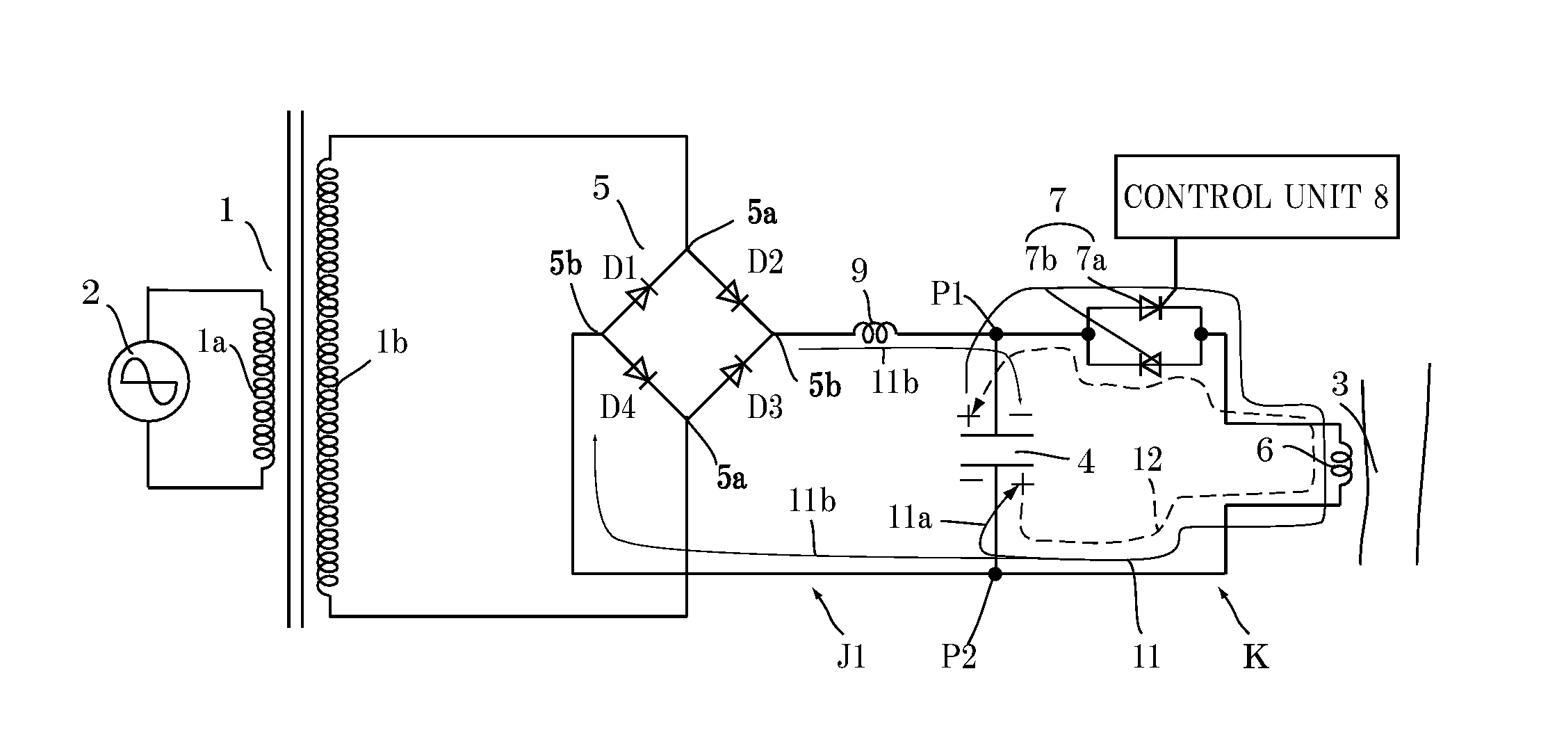
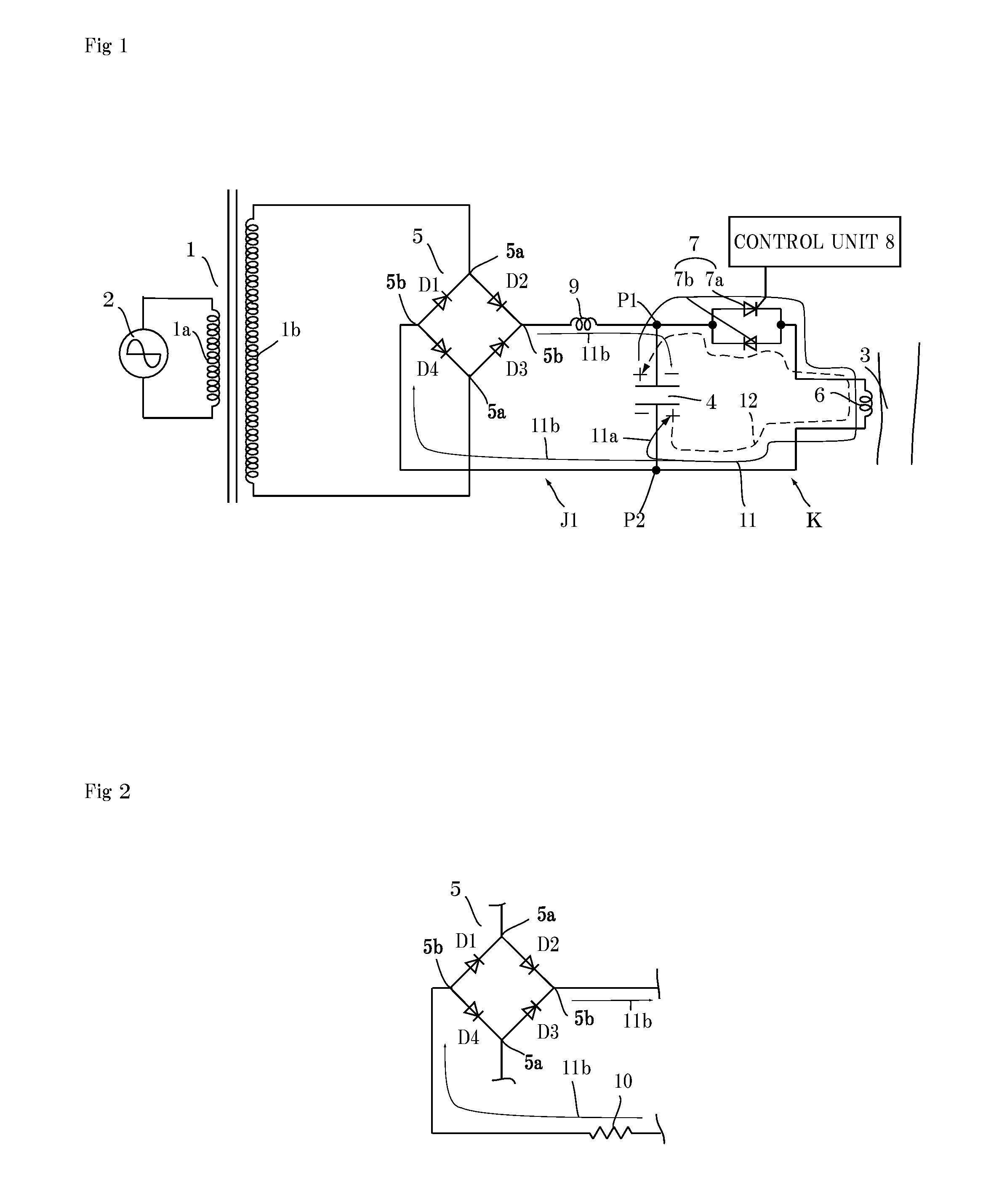
[0076]A successive magnetic pulse magnetic stimulation device in which the total inductance L of the charging circuit section J1 or J2 is 4.3 H, the total DC resistance is 0.5Ω, the capacitance of the charging / discharging capacitor 4 is 100 μF, and the inductance of the pulse coil 6 is 15 μH was produced on the basis of the calculation results in FIG. 15 according to the present invention. The circuit configuration was set as the configuration in FIG. 2 or FIG. 5. The output voltage of the full-wave rectifying circuit 5 was changed in a range of 350 to 600 V, the cycle of the trigger signal to the discharging element 7 was changed between 20 to 100 milliseconds, and successive magnetic pulses were generated. According to “mathematical formula 2”, the time when the charge current flows into the capacitor 4 of the discharging circuit section K is 33 milliseconds (30 Hz). According to an experiment, in the case of successive magnetic pulses of 10 to 30 Hz, regarding each volta...


PUM


Abstract

A smaller-sized, more lightweight, and power-saving successive magnetic pulse device is provided. A discharging circuit section K is configured by connecting, in series in a loop, a magnetic therapy pulse coil 6 configured to generate an eddy current in a target part 3, a charging/discharging capacitor 4, and a switching semiconductor element 7 configured to supply a discharge current from the charging/discharging capacitor 4 to the pulse coil 6. A step-up transformer 1 includes a primary-side coil 1a connected to an AC power supply 2 and a secondary-side coil 1b connected to input terminals 5a of a full-wave rectifying circuit 5. A control unit 8 is connected to a switching semiconductor element 7 and controls conduction timing of the switching semiconductor element 7. The full-wave rectifying circuit 5 has output terminals 5b connected to both terminals P1 and P2 of the charging/discharging capacitor 4, respectively. An inductor 9 is connected between the output terminal 5b of the full-wave rectifying circuit 5 and the terminal P1 of the charging/discharging capacitor 4.

Description

TECHNICAL FIELD[0001]The present invention relates to a medical successive magnetic pulse generation device for causing sustained great contraction in muscles by stimulating peripheral nerves with successive magnetic pulses.BACKGROUND ART[0002]A pulse current is used in wide industrial fields, and many products including industrial high-voltage pulse devices, such as an electric dust collector, a plasma generator, and a laser, and medical low-frequency therapeutic devices for moving muscles with a weak pulse current, have been put into practical use. Many pulse currents for industrial equipment are characterized by a high voltage (3 to 10 kV), a low current (several milliamperes to several amperes), a high frequency (30 to 100 kHz), and a narrow pulse width (1 to 10 μs). The reason for this is that as the voltage is higher and the pulse width is narrower, higher energy can be generated momentarily.[0003]Regarding such a pulse power supply for the purpose of generating a sharp high-v...

Claims


Application Information

Patent Timeline
IPC IPC(8): A61N2/02A61N2/00
CPCA61N2/006A61N2/02
Inventor ABE, TOSHIHIKOMORI, HITOSHIYASHIMA, KENJIMORI, KAZUMITAKAGI, TOSHIYUKIIZUMI, SHINICHIKANETAKA, HIROYASUNAGATOMI, RYOICHI
Owner IFG
Why Eureka
Try Eureka