
Electrochemical cell and method of making the same

a technology of electrochemical cells and electrodes, applied in the direction of secondary cells, cell components, sustainable manufacturing/processing, etc., can solve the problems of high reactive metal anodes, significant and well documented safety hazards, and the rapid loss of accessible capacity of metallic lithium anodes, etc., to maximize the volumetric or gravimetric energy density

Active Publication Date: 2016-06-16
VIKING POWER SYST PTE LTD
View PDF0 Cites 29 Cited by
  • Summary
  • Abstract
  • Description
  • Claims
  • Application Information

AI Technical Summary

Benefits of technology

This invention has various objectives, aspects, features, and advantages. The technical effects will be explained in detail in the following description and claims.

Problems solved by technology

Excess-anode devices constructed in this manner minimize the risk of plating lithium metal during charging which is widely believed to be detrimental to cell cycle life and safety.
However lithium metal anodes are known to be highly reactive, which on cycling continuously generate high surface area lithium and decomposition products.
The generation of high surface area metallic lithium and decomposition products lowers the onset of thermal instability leading to significant and well documented safety hazards.
Additionally, metallic lithium anodes are known to rapidly lose accessible capacity through the formation of finely divided and electrically isolated regions of metallic lithium.
While such open-system cells utilize air as an active material, the capacity of the cathode electrode (P) is well defined and limited to a finite value.
However, the cell reported by Neudecker suffers from a prohibitively low electrode loading, generally less than 0.1 mAh / cm2, required to meet a practical rate capability.
However, all solid-electrolyte cells as well as hybrid barrier layer with liquid electrolyte cells suffer from major disadvantages in terms of manufacturability and rate performance.
The portion of the dendrite protruding into the electrolyte increases on cycling until it spans the electrolyte thickness, causing a short circuit.
For lithium-ion batteries with carbonaceous anode, lithium deposition may occur under harsh charging conditions such as overcharging or charging at low temperatures.
The authors state that metal deposition is always disadvantageous, and that the solution includes ensuring that the battery design has a sufficiently large excess of anode or N / P>1.

Method used


Image

  • Electrochemical cell and method of making the same
  • Electrochemical cell and method of making the same
  • Electrochemical cell and method of making the same

Examples


example 1

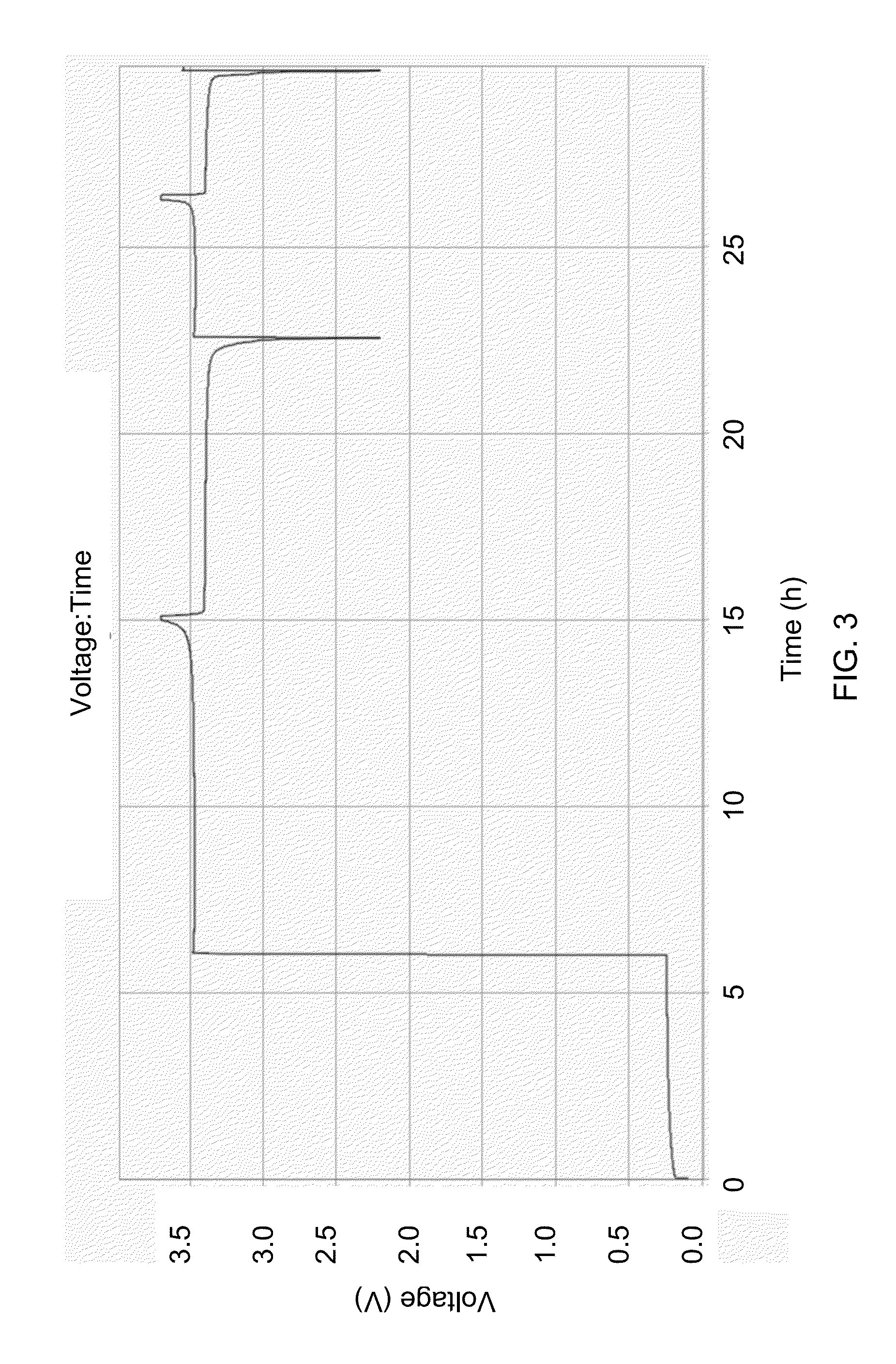
[0118]FIG. 3 shows a typical voltage profile of a cell containing N / P ratio + transfers from the cathode to plate out upon the anode Cu substrate, lowering that negative electrode potential to near −3 V vs. SHE. The corresponding cell potential jumps to about 3.5 V, and rises monotonically thereafter to charge cutoff at about 3.7 V. Thereafter discharge and charge can occur anywhere within this window as the anode electrode potential remains low due to the potential of the decomposition products upon the surface. This cell contains a lithium iron phosphate cathode assembled vs. a copper negative electrode substrate and immersed in a lithium hexafluorophosphate in ethylene dicarbonate and dimethyl carbonate-based electrolyte. All cycling was conducted at room temperature. The first cycle was conducted at 17 mA / g while the subsequent cycling is 34 mA / g.

example 2

[0119]FIG. 4 shows a typical voltage profile of a cell containing an N / P ratio + transfers from the cathode to plate out upon the anode substrate, lowering that negative electrode potential to near −3 V vs. SHE. The corresponding cell potential jumps to about 3.8 V, and rises monotonically thereafter to charge cutoff at about 4.4 V. Thereafter discharge and charge can occur anywhere within this window as the anode electrode potential remains low due to the potential of the decomposition products upon the surface. This contains a lithium nickel manganese cobalt oxide cathode assembled vs. a copper negative electrode substrate and immersed in a lithium diflurooxolatoborate in ethylene dicarbonate and dimethyl carbonate-based electrolyte. All cycling was conducted at room temperature and cycle was conducted at C / 5 while the subsequent cycling is 2 C.

example 3

[0120]FIG. 5 shows a typical voltage profile of a cell having N / P ratio <0.9 in the charged state. Herein we show the corresponding cell voltage profile for a cell containing a high capacity transition metal oxide wherein metal ions electrodeposit onto the negative electrode substrate during the initial charging. Thereafter the cell charges and discharges while plating and stripping the metal deposited from the cathode during the initial charge. This example shows a high capacity metal anode cell with an average voltage quite similar to that obtained by electrodepositing Li metal as depicted in FIG. 3.

[0121]FIG. 6-FIG. 9 show various characteristics of the presently disclosed cells, all constructed in a manner such that the Li metal anode is formed in-situ on the first charge of the cell by plating onto an inert current collector. The data for shown in FIG. 6 through FIG. 9 are for cells cycled at room temperature at a variety of charge and discharge rate combinations of commercial ...


PUM

PropertyMeasurementUnit
temperaturesaaaaaaaaaa
Coulombic efficiencyaaaaaaaaaa

Abstract

A secondary cell comprising a positive cathode electrode of capacity P (mAh) in communication with a liquid or gel electrolyte; an negative anode electrode of capacity N (mAh) in communication with the electrolyte; and a separator permeable to at least one mobile species which is redox-active at least one of the anode and the cathode; designed and constructed such that the anode capacity N is smaller than that of the cathode capacity P, hence N / P<0.9.

Description

CROSS-REFERENCE TO RELATED APPLICATIONS[0001]This application claims priority to and the benefit of co-pending U.S. provisional patent application Ser. No. 62 / 091,413, filed Dec. 12, 2014, which application is incorporated herein by reference in its entirety.FIELD OF THE INVENTION[0002]The invention relates to electrochemical cells in general and particularly to secondary electrochemical cells.BACKGROUND OF THE INVENTION[0003]Rechargeable or secondary electrochemical storage devices or batteries have wide-ranging applications and development of improved battery performance is a long-standing goal. Maximizing the volumetric or gravimetric energy density (i.e. minimizing the cell volume or mass) is an important and closely tracked performance metric. Rechargeable electrochemical cells such as Li-ion and NiMH use an electrochemically active, non-metallic, insertion material at the negative electrode or anode. However, many electrochemical storage systems involve the use of an electroch...

Claims


Application Information

Patent Timeline
Patent Type & Authority Applications(United States)
IPC IPC(8): H01M4/04H01M10/052H01M4/1395H01M4/38
CPCH01M4/0452H01M4/382H01M2004/027H01M4/1395H01M10/052H01M4/381H01M10/054H01M10/0568H01M10/42H01M2004/021H01M2010/4292H01M2300/0025H01M4/0445H01M4/134Y02E60/10Y02P70/50H01M10/058Y02T10/70
Inventor FISCHER, CHRISTOPHER CARLDOE, ROBERT ELLISEAGLESHAM, DAVIDTRAHAN, MATTHEW JOSEPHGMITTER, ANDREW
Owner VIKING POWER SYST PTE LTD
Learn More