Photodetector focal plane array systems and methods

a technology of focal plane array and photodetector, applied in the field of imaging systems and methods, to achieve the effects of reducing dark current, increasing speed, and improving sensitivity

Active Publication Date: 2016-06-30
THE UNIV OF NORTH CAROLINA AT CHAPEL HILL +1
View PDF0 Cites 4 Cited by
  • Summary
  • Abstract
  • Description
  • Claims
  • Application Information

AI Technical Summary

Benefits of technology

[0011]The present invention is devoted to new FPA systems and methods providing enhanced sensitivity, reduced dark current, increased speed, and improved angular characteristics. The proposed systems and methods are based on the assembly of an array of dielectric microspheres at the top of the FPA in such a way that individual microspheres are positioned above the photosensitive regions of the FPA. These regions can be represented by pin junctions containing quantum wells, quantum dots, strained-layer superlattices or other materials with light absorption properties in the desired spectral range. Dielectric microspheres provide strong concentration of electromagnetic power, sometimes termed the “photonic nanojet” effect, directly into the photosensitive regions of the FPA. This is provided through the mesas fabricated at the surface of FPA. This leads to improved efficiency in the collection of light in such structures. The subwavelength width of the photonic nanojets allows using mesas with wavelength-scale dimensions, which results in reduced dark current and increased frequency response of the FPAs. The parameters of the microspheres are optimized for a given FPA to achieve the best focusing properties at the optimal depth inside the structure. The typical values of the index of refraction (n) and the diameter (D) of the microspheres are within 1.4<n<2.0 and 2λ<D<100λ ranges, by way of example only. The light collection efficiency is improved due to the fact that the sphere diameter, D, can be much larger than the pixel diameter, d. AOV is improved due to the fact that microspheres with spherical shape have stronger focusing capability compared to dome-shaped COTs microlenses. Another important factor is that the microspheres can be easily fabricated using relatively high-index materials (n>1.6). Such microspheres are particularly efficient for reducing f. In fact, the spheres with n˜1.8 focuses the collimated beam close to the back (not illuminated) surface of the sphere which means that the condition f˜D / 2 can be approached in such structures. Simple estimation based on Eq. (1) shows that d=12 μm mesas integrated with D=50 μm spheres should possess AOV=27 deg which is significantly larger angle compared to AOV provided by COT microlenses. Two times larger spheres with D=100 μm should still have sufficiently large AOV=13.7 deg. In addition to AOV advantage, such spheres would also provide significantly higher efficiency of collection of light compared to the same structures without spheres. The efficiency advantage can be estimated as (1−k)2×(D / d)2, where k is the total amplitude reflection coefficient of the microspherical surface. The efficiency advantage on the order of 50-60 can be obtained for d=12 μm mesas integrated with D=100 μm spheres. In the proposed designs there is a trade-off between the light collection efficiency advantage over bare structures (no spheres) and AOV advantage over structures integrated with COT microlenses. Generally speaking, larger spheres favor higher light collection efficiencies by the expense of AOV. However, in terms of the parameters required for imaging applications, the proposed structures over perform bare structures and structures equipped with COT microlenses. The positioning of a large number of microspheres can be performed by various self-assembly and micro-manipulation techniques. After that, the microspheres are fixed using glues, epoxies, or, more generally, materials with the ability to solidify, photocurable materials, temperature-curable materials, etc., or by other such techniques. In particular, a deliberate temperature treatment can be used to slightly melt of soften the material of the spheres or material of the adjacent layers to fix the spheres exactly above the detector mesas.
[0012]Similar mechanisms of the enhancement of light collection efficiency and improvement of AOV can be realized by using a microcylindrical lens arrays assembled at the top of the photodetector arrays. In this case, the focusing is provided in only one direction perpendicular to the microcylinder axis. This means that the enhancement of light collection can be smaller than that for spheres, but it can still be significantly improved compared to that in bare photodetector arrays. The advantage of microcylindrical arrays is that they can be obtained from microfibers with relatively well reproducible diameters. In fact, standard single-mode telecom fibers with extremely well preserved diameter 125 μm can be used for this purpose. Another advantage of such structures is connected with their potentially simple manufacturability (close-packed array of microfibers) and their extremely large area fill factor which can reach unity and exceeds the area fill factor for close-packed arrays of microspheres.

Problems solved by technology

However, in terms of the parameters required for imaging applications, the proposed structures over perform bare structures and structures equipped with COT microlenses.

Method used


Image

  • Photodetector focal plane array systems and methods
  • Photodetector focal plane array systems and methods
  • Photodetector focal plane array systems and methods

Examples


Embodiment Construction

[0021]By way of enabling background, prior work has taken place in three main areas: i) developing the general concept of photonic nanojets; ii) developing techniques for the self-assembly of microspheres; and iii) developing micro-assembly technologies, such as vacuum or suction tweezers and grippers.

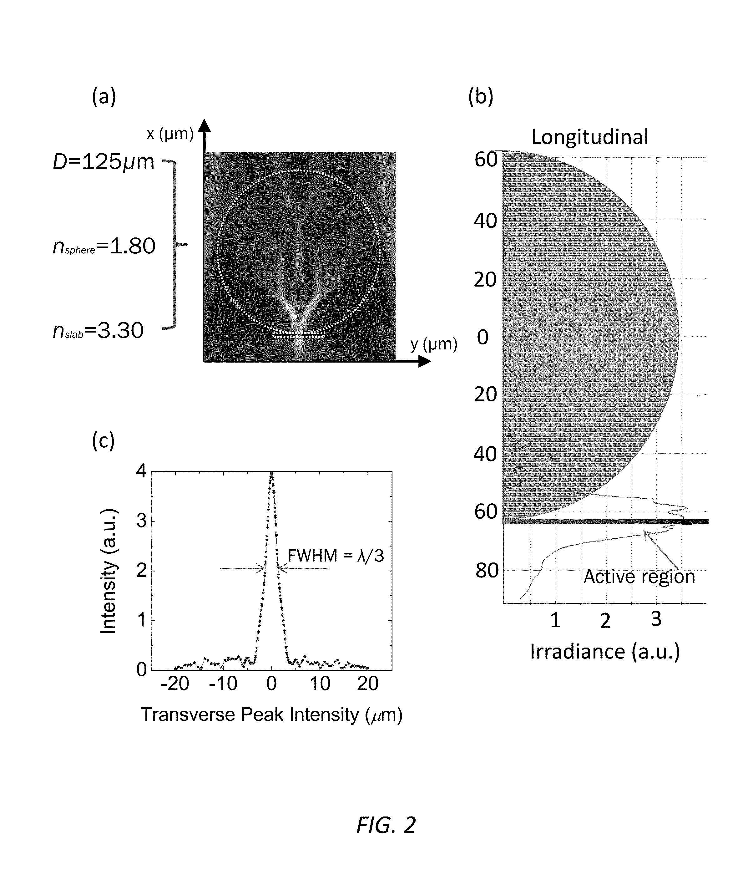
[0022]Photonic nanojets. It has been proposed that dielectric spheres can be used for obtaining tightly focused beams with lateral dimensions which can be smaller than the diffraction limit. Such tightly focused beams have been termed “photonic nanojets.” These photonic nanojets appear for a wide range of diameters of microspheres, typically in a 2λ


PUM


Abstract

A photodetector focal plane array system, comprising: a substrate comprising a plurality of photosensitive regions; and a microcomponent disposed adjacent to each of the plurality of photosensitive regions operable for receiving incident radiation and directing a photonic nanojet into the associated photosensitive region. Optionally, each of the microcomponents comprises one of a microsphere and a microcylinder. Each of the microcomponents has a diameter of between ˜λ and ˜100λ, where λ is the wavelength of the incident radiation. Each of the microcomponents is manufactured from a dielectric or semiconductor material. Each of the microcomponents has an index of refraction of between ˜1.4 and ˜3.5. Optionally, high-index components can be embedded in a lower index material. The microcomponents form an array of microcomponents disposed adjacent to the substrate.

Description

FIELD OF THE INVENTION[0001]The present invention relates generally to imaging systems and methods, such as military and civil infrared (IR) imaging systems and methods and the like. More specifically, the present invention relates to photodetector focal plane array (FPA) systems and methods for use with such imaging systems and methods.BACKGROUND OF THE INVENTION[0002]The present invention relates generally to FPAs. FPAs are widely used in military and civil IR imaging systems and the like, such as systems for guidance and control, target acquisition, surveillance, laser range-finding, fiber-optic and free-space communications, thermal imaging, and other applications. More specifically, the present invention addresses the problem of designing FPAs that are capable of detecting weak optical images with a sufficiently large angle-of-view (AOV).[0003]For IR applications, the photosensitive material of FPAs is typically fabricated from narrow-band gap semiconductors, such as Hg1-xCdxTe...

Claims


Application Information

Patent Timeline
Patent Type & Authority Applications(United States)
IPC IPC(8): H01L27/146
CPCH01L27/14627H01L27/14685H01L27/14649G02B13/0085H01L27/14625
Inventor ASTRATOV, VASILY N.ALLEN, JR., KENNETH W.LIMBEROPOULOS, NICHOLAOS I.URBAS, AUGUSTINEDURAN, JOSHUA M.
Owner THE UNIV OF NORTH CAROLINA AT CHAPEL HILL
Why Eureka
Try Eureka