Perfusion bioreactor

a bioreactor and cell technology, applied in the field of cell culture, can solve the problems of poor tissue formation, unsatisfactory clinical potential of current treatments for patients in need of complex skeletal reconstruction, and inability to grow centimeter-sized bone grafts for clinical translation

Active Publication Date: 2016-07-07
NEW YORK STEM CELL FOUND
View PDF3 Cites 4 Cited by
  • Summary
  • Abstract
  • Description
  • Claims
  • Application Information

AI Technical Summary

Problems solved by technology

Nevertheless, current treatments for patients in need of complex skeletal reconstruction have never reached full clinical potential and can be associated with life-threatening complications.
However, static cultures are not optimal to grow centimeter-sized bone grafts for clinical translation due to poor nutrient supply and removal of metabolic waste.
Under these conditions, in fact, mass transport occurs only via diffusion, which is not sufficient to support cell survival and proliferation inside the core of large cell / scaffold constructs, resulting in necrosis and poor tissue formation.
In addition, cell proliferation and matrix synthesis at the construct periphery over the culture period further impede medium diffusion and contribute to the formation of a nutrient gradient that drive cell migration towards the substitute borders (Goldstein, A. S., Juarez, T. M., et al.
On top of this, culture in static conditions does not allow provision of those biophysical stimuli that are critical for functional regeneration (Yeatts, A. B., Fisher, J. P. Bone tissue engineering bioreactors: dynamic culture and the influence of shear stress.
Therefore, the convective forces generated by the perfusion pump mitigate the nutrient concentration gradients principally at the surface of the cell / scaffold constructs, thus limiting the size of bone substitutes that can be engineered using these systems.
While biomimetic tissue engineering strategies have been explored for ex vivo cultivation of functional bone substitutes by interfacing osteocompetent cells to biomaterials under appropriate culture conditions in bioreactors, engineering large and geometrically complex bone grafts for extensive skeletal reconstructions remains problematic using current engineering approaches.
In particular, as discussed above, culture of large bone grafts is problematic using common perfusion bioreactors, due to the flow resistance caused by the large size of the graft.
The development of newly formed bone tissue progressively limits the medium perfusion, with negative consequences on the functionality of the perfusion system and graft viability.

Method used


Image

  • Perfusion bioreactor
  • Perfusion bioreactor
  • Perfusion bioreactor

Examples


example 1

Use of Bioreactors and Scaffolds to Engineer Large Bone Grafts

[0178]Computed tomography is used to generate anatomically accurate 3D models of traumatic or pathological skeletal defects. Digital models of skeletal defects are then edited using computer-aided design (CAD), and sliced off into pieces of adequate thickness, which allow effective engineering of functional bone tissue using perfusion bioreactors. The partitioned bone defect files are thus imported in computer-aided manufacture (CAM) software to drive the fabrication of geometrically defined biomaterial scaffolds using a combination of computer-controlled milling, rapid prototyping and casting technologies. The partitioned bone defect files are also used to drive the computer-controlled milling or 3D printing of customized perfusion bioreactors that can accommodate the cell / scaffold construct in a press-fit fashion under direct perfusion conditions (see FIG. 14, top panel). Patient-specific bone and blood vessel forming c...

example 2

Computer-Aided Design and Manufacture of Bioreactors and Scaffolds

[0179]Bioreactors and scaffolds provided by the invention can be designed and manufactured as described herein. In some embodiments, computer-aided design (CAD) and computer-aided manufacture (CAM) are used to design and manufacture the bioreactors and / or scaffolds. A person having ordinary skill in the art will appreciate that any other methods of designing and manufacturing may be used to generate bioreactors and / or scaffolds according to the present invention.

[0180]Digital models of skeletal defects can be created using CAD software, e.g., Autocad, Solidworks, ProE, and Creo. Reference models of skeletal defects in CAD can be edited and segmented into smaller complementary sub-parts which represent bone segments that can be cultured in perfusion bioreactors without affecting the perfusion system. The segmented bone sample files can be saved in compatible formats, for example, IGES or SLT formats, and imported in CA...

example 3

Engineering Vascularized Bone Grafts for Repairing Large Skeletal Defects

[0183]Introduction

[0184]This Example proposes a strategy for engineering vascularized bone grafts from human induced pluripotent stem cells (hiPSCs) for enhanced healing of complex skeletal defects. In particular, the ability to derive autologous osteogenic and vascular cells constituting healthy bone from hiPSCs for any patient in virtually unlimited numbers represents an unprecedented therapeutic resource. Vascularized bone substitutes will be engineered using a biomimetic scaffold-bioreactor approach to bone development. Computer-aided and rapid prototyping technologies will allow the preparation of bone substitutes of any shape and size. Digital models of large bone defects will be created and then segmented in complementary sub-parts that will be used to produce customized biomaterial scaffolds and bioreactors via computer-aided design and manufacturing technologies, such as 3D printing (see FIG. 14). The ...


PUM

PropertyMeasurementUnit
thicknessaaaaaaaaaa
thicknessaaaaaaaaaa
angleaaaaaaaaaa

Abstract

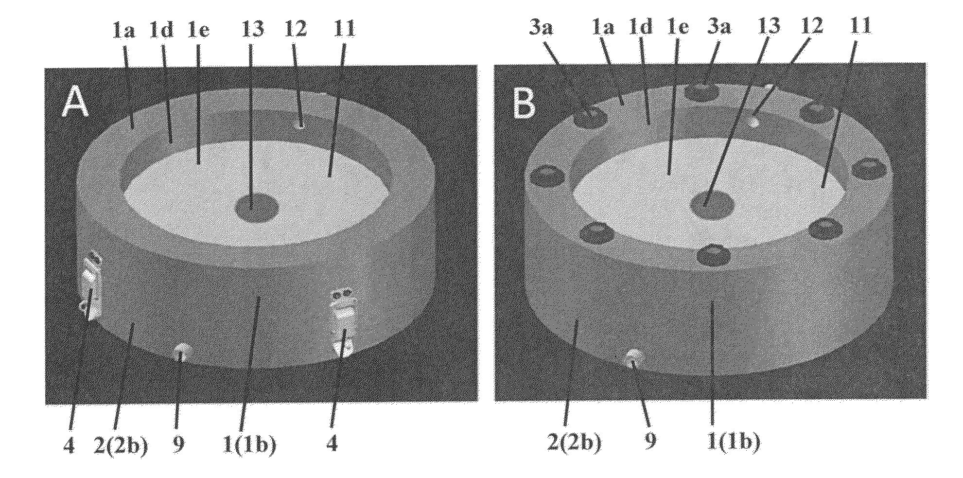
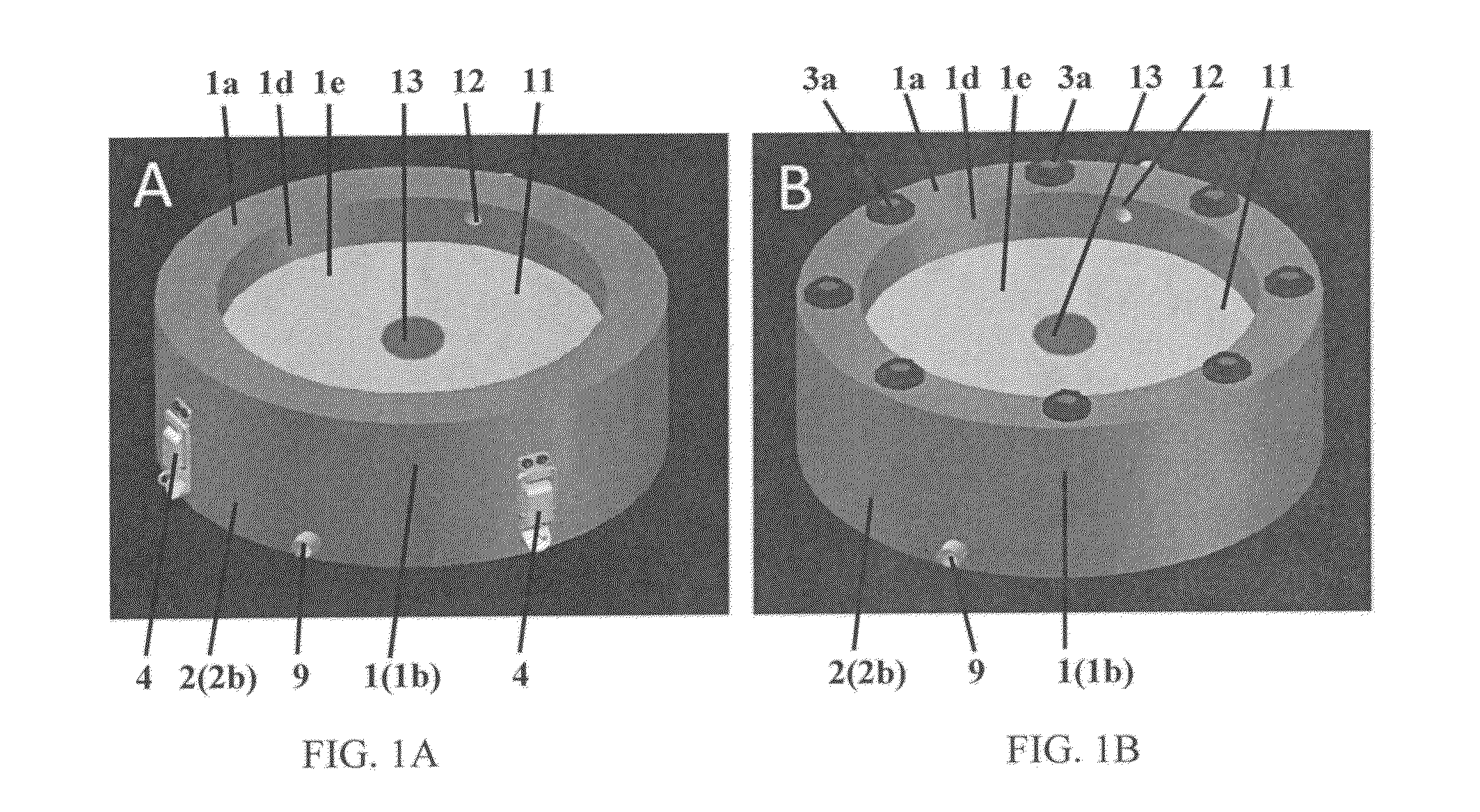
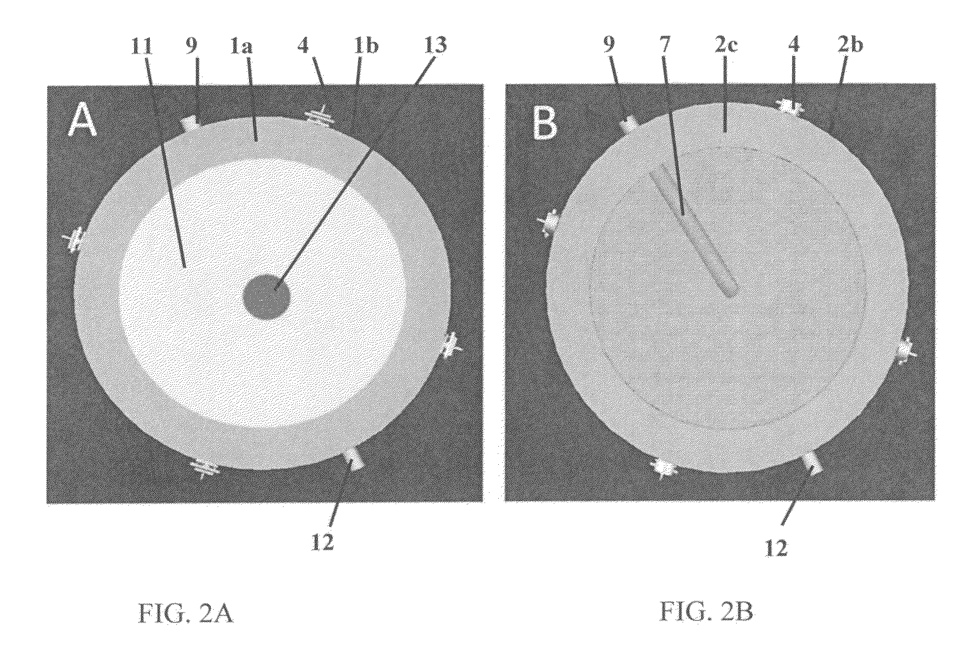
In some embodiments the present invention provides perfusion bioreactors and cell culture scaffolds suitable for the preparation of tissue grafts, such as bone tissue grafts. In some embodiments, the perfusion bioreactors comprise a graft chamber and/or a graft chamber insert configured to hold a tissue graft having a certain shape and/or certain dimensions, and/or to allow culture of such tissue grafts under press-fit direct perfusion conditions. In some embodiments, the perfusion bioreactors comprise an equilibration chamber.

Description

CROSS-REFERENCE TO RELATED APPLICATIONS[0001]This application claims the benefit of priority of U.S. Provisional Patent Application No. 62 / 087,614, filed Dec. 4, 2014, and also claims the benefit of priority of International Patent Application No. PCT / US2014 / 072579, filed Dec. 29, 2014, which claims the benefit of priority of U.S. Provisional Patent Application No. 62 / 087,614, filed Dec. 4, 2014, and U.S. Provisional Patent Application No. 61 / 921,915, filed Dec. 30, 2013, the contents of each of which are hereby incorporated by reference in their entireties.COPYRIGHT AND INCORPORATION BY REFERENCE[0002]A portion of the disclosure of this patent document contains material that is subject to copyright protection. The copyright owner has no objection to the facsimile reproduction by anyone of the patent document or the patent disclosure as it appears in the Patent and Trademark Office patent file or records, but otherwise reserves all copyright rights whatsoever.BACKGROUND INFORMATION[...

Claims


Application Information

Patent Timeline
Patent Type & Authority Applications(United States)
IPC IPC(8): C12M1/00C12M1/12C12M3/00
CPCC12M29/10C12M25/00C12M23/46C12M21/08A61F2002/4648A61K35/12C12M25/14C12N5/0062A61F2/28A61F2/2846A61F2/30756A61F2/30942A61F2002/2835A61F2002/30759A61F2002/30762A61F2002/30766A61F2002/30943A61F2002/30952A61L27/3821C12N5/0607
Inventor MARIA DE PEPPO, GIUSEPPE
Owner NEW YORK STEM CELL FOUND
Why Eureka
Try Eureka