Graphene modification

Active Publication Date: 2016-07-14
UK RES & INNOVATION LTD
View PDF5 Cites 1 Cited by
  • Summary
  • Abstract
  • Description
  • Claims
  • Application Information

AI Technical Summary

Benefits of technology

[0064]It is a key advantage of the invention that through the choice of atoms/conditions which are used to treat the graphene, it can be modified chemically whilst being physically unaltered. In other words, the inventors are able to change the bond structure within the graphene, but not remove atoms from the graphene lattice which would disrupt its physical properties vital to its use in EM.
[0065]The inventors teach that even very low proportions of hydrogenation (such as 0.1 to 20% hydrogen per carbon) can be enough to restore sufficient hydrophilicity to permit reliable deposition of biological molecules onto the surface for EM.
[0066]In the field of material science, a substance called graphane has been produced. Graphane is a fully hydrogenated carbon sheet. In graphane, each carbon is sp3 bonded to 3 carbons, plus a hydrogen. By contrast, the inventors teach the partial hydrogenation of graphene. In this way, the characteristics of graphene are preserved, whilst advantageously providing enough hydrogenation to permit distribution of biological molecules across the graphene surface, facilitating excellent results in EM studies. It is an advantage of the invention that the lattice structure is completely preserved. Without wishing to be bound by theory, of course the precise bond lengths of the hydrogen-bonded carbons in the partially hydrogenated graphene of the invention may vary compared to the bond lengths of entirely unhydrogenated graphene. However, what is important is that the hexagonal lattice structure of the graphene is preserved according to the invention.
[0067]In the c

Problems solved by technology

However, graphene support films are not currently used for electron microscopy of biological molecules.
This has led to insurmountable problems precluding reliable deposition of biological molecules such as proteins onto the graphene.
In addition, the pristine graphene surface is easily contaminated, which renders them no bett

Method used


Image

  • Graphene modification
  • Graphene modification
  • Graphene modification

Examples


example 1

Hydrogenation of Graphene

[0203]In this example we demonstrate a method for making a partially hydrogenated graphene.

[0204]We apply a hydrogen ion or hydrogen atom to the surface of the graphene (in this example by a hydrogen plasma).

[0205]The hydrogen plasma is applied at an energy in the range 1 to 21 eV.

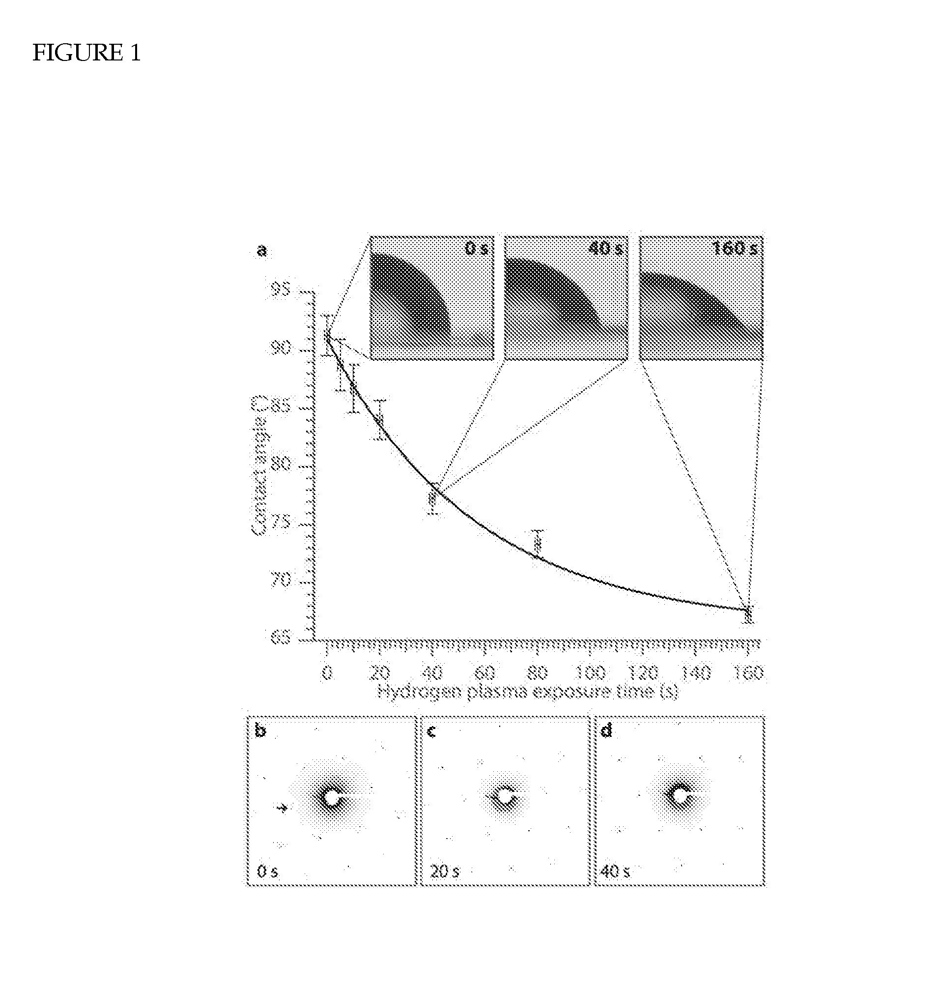
[0206]To measure the change in hydrophobicity of a graphene surface in response to hydrogenation (in this example by a hydrogen plasma), we measured the static contact angle between water, air and graphene as grown by CVD on a copper substrate. A 1 μl water droplet was applied to graphene on copper and imaged using a calibrated optical microscope attached to a digital camera (FIG. 1a insets). Each measurement was repeated for sequentially increasing doses of exposure to a pure hydrogen plasma at 50 mTorr and with energy (electron temperature) estimated to be approx. 10-15 eV, as detailed in the methods. The results of these measurements are shown in FIG. 1a. We found that the conta...

example 2

Graphene Cleaning

[0209]In this example we demonstrate that small atom plasma treatment such as hydrogen plasma treatment removes surface contaminants on graphene.

[0210]In particular we show a method for cleaning a graphene surface, comprising contacting said graphene surface with a hydrogen plasma. The time of contact is a time sufficient to remove surface impurities, as shown below.

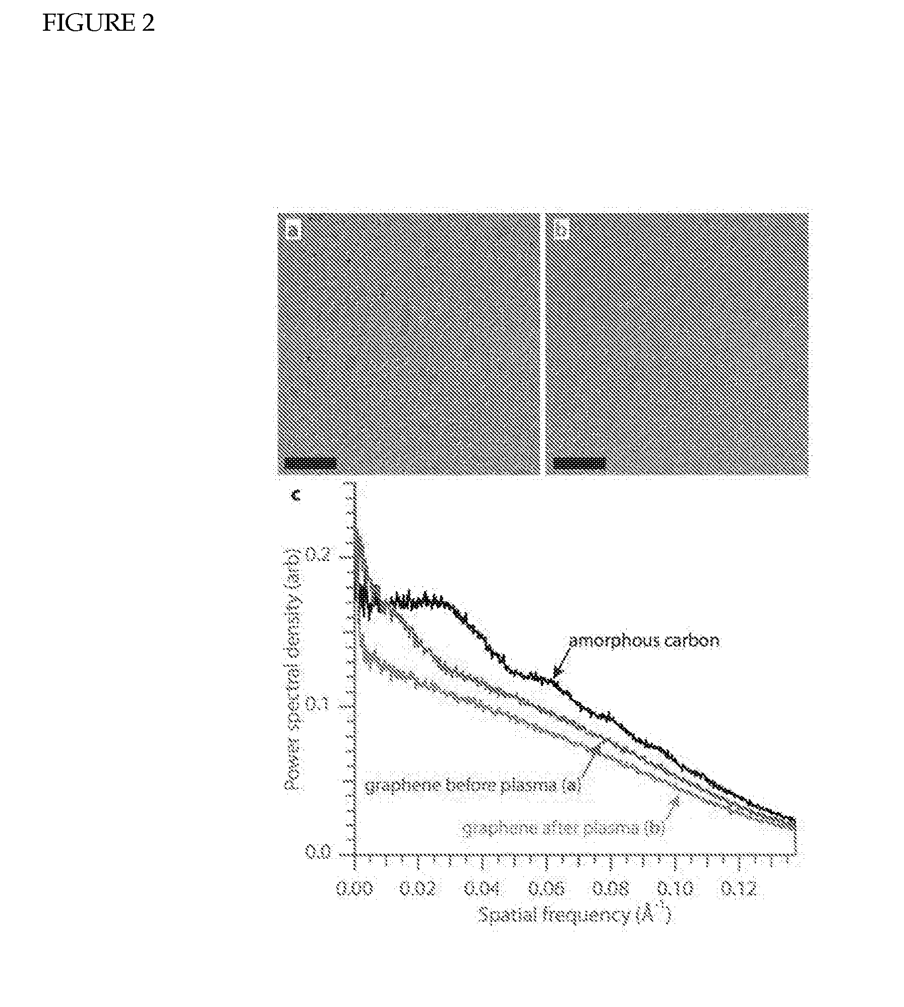
[0211]We studied graphene's properties as a substrate for electron microscopy before and after plasma treatment, and compared it to amorphous carbon. Suspended graphene as transferred to a Quantifoil grid, when examined with electrons under conditions typical for imaging proteins (300 keV, 25 e− / Å2, 39000× magnification), shows significant amounts of surface contamination (FIG. 2a and FIG. 7a). Exposing the graphene to 30 seconds of hydrogen plasma removes most of the surface contamination (FIG. 2b and FIG. 7b) but increases the background signal level in the image slightly due to the addition of hydroge...

example 3

Tuning of Graphene Surface

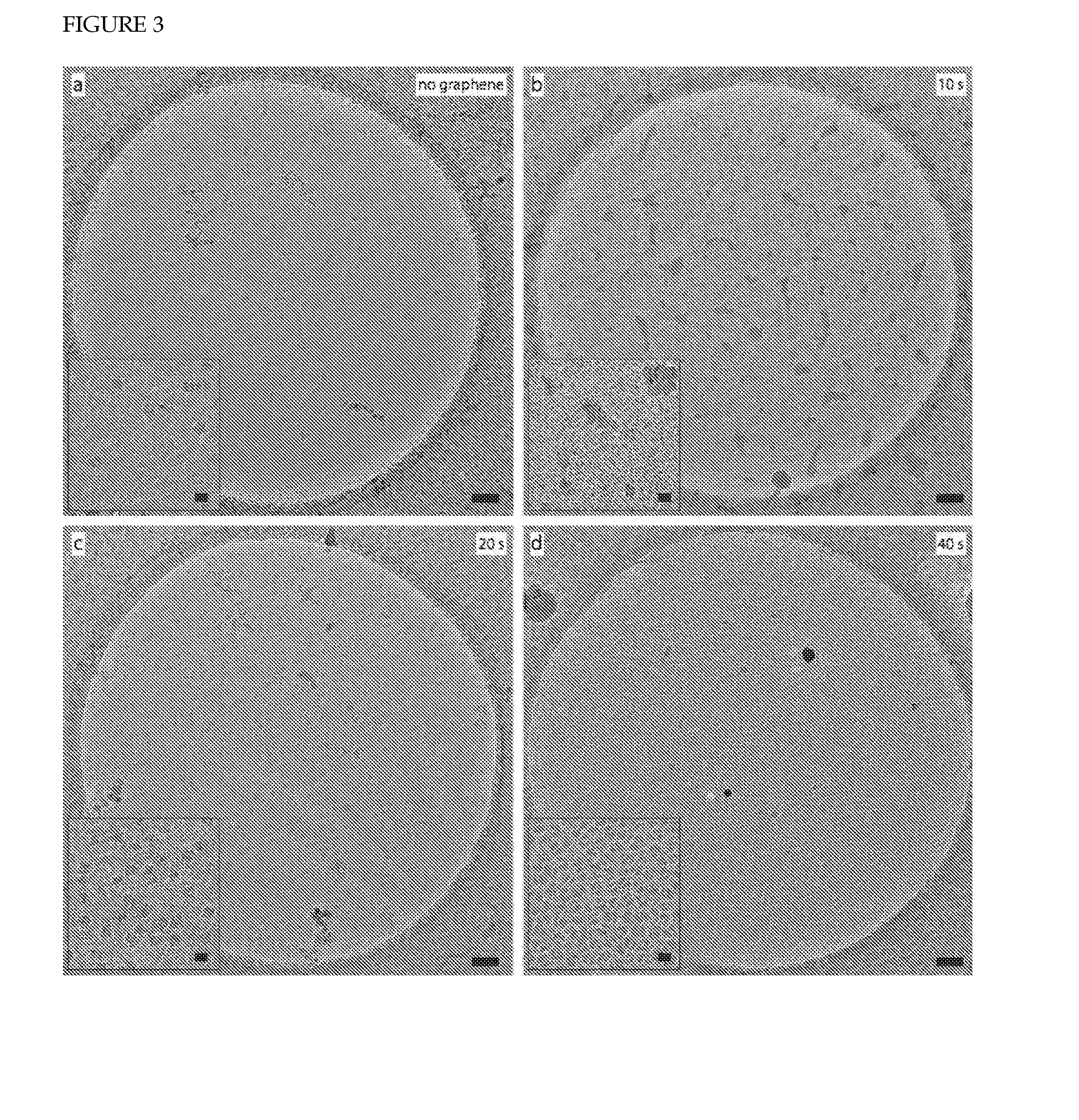
[0213]In this example we show the control of the adsorption of proteins to graphene by partial hydrogenation of the graphene according to the present invention. Having shown that we can control the hydrophobicity of graphene, we then tested hydrogen plasma treated graphene as a substrate for cryo-EM using 70S ribosomes. We transferred monolayer graphene onto Quantifoil EM grids, subjected them to various doses of hydrogen plasma, and used them to prepare vitrified samples of 70S ribosomes. FIG. 3a shows that on grids without graphene, very few 70S particles are visible in the vitreous ice, as most are attracted to the surface of the Quantifoil carbon and the edges of the holes (note the ring of ribosomes at the edge of the hole). Using identical freezing and blotting conditions with graphene grids treated with 10 seconds of hydrogen plasma, only small patches of vitreous ice were visible (FIG. 3b). This is indicative of the incomplete wetting of the graphen...


PUM


Abstract

Some embodiments are directed to a support for receiving a biological sample, the support comprising at least one support member, and including graphene attached to the support member. The graphene is partially hydrogenated graphene. Some embodiments are also directed to use of a partially hydrogenated graphene surface to support a biological molecule for electron microscopy. Some other embodiments are also directed to a method for making a partially hydrogenated graphene. The method includes applying a hydrogen ion or hydrogen atom to the surface of graphene. The hydrogen ion or hydrogen atom is applied at an energy in the range 1 to 21 eV. A sensor comprising a surface capable of adsorbing a biological molecule thereto is also disclosed, wherein said surface includes partially hydrogenated graphene.

Description

FIELD OF THE INVENTION[0001]The invention is in the field of supports for biological samples, such as supports for biological molecules.BACKGROUND TO THE INVENTION[0002]Improved electron microscopes, more stable cryo-stages and direct electron detectors with high quantum efficiency have recently brought about a revolution in biological electron microscopy (EM), enabling near atomic resolution 3D structures for large molecules and viruses1-3. Electron cryo-microscopy (cryo-EM) is used to determine protein structures. It is a method still under development and the resolutions of resulting 3D reconstructions have been steadily increasing. With current methodology, near-atomic resolutions can be obtained. As the resolutions increase further, the pharmaceutical industry will hope to exploit this technique, probably in parallel with x-ray crystallography, to understand how drugs bind to their protein targets. Still, grid design and preparation have remained largely unchanged since they we...

Claims


Application Information

Patent Timeline
IPC IPC(8): H01J37/20B08B7/00G01N33/543H01J37/26C01B31/04
CPCH01J37/20H01J37/26C01B31/0484H01J2237/2007G01N33/54393B08B7/0035H01J2237/2602C01B31/0492G01N23/20025G01N23/04C01B32/194C01B32/196C01B32/182B01J19/088
Inventor RUSSO, CHRISTOPHER J.PASSMORE, LORI A.
Owner UK RES & INNOVATION LTD
Why Eureka
Try Eureka