COG Dielectric Composition For Use With Nickel Electrodes

a dielectric composition and nickel electrode technology, applied in the direction of fixed capacitor electrodes, fixed capacitors, electrical equipment, etc., can solve the problems of reduced resistivity, reduced dielectric layers, and devices with a shorter life of insulation resistance (ir) , to achieve the effect of excellent reliability and small dielectric loss

Active Publication Date: 2016-08-18
FERRO CORP
View PDF2 Cites 7 Cited by
  • Summary
  • Abstract
  • Description
  • Claims
  • Application Information

AI Technical Summary

Benefits of technology

[0008]The present invention provides a dielectric composition that can be used to make ceramic multilayer capacitors compatible with internal electrodes containing base metals such as nickel or nickel alloys. Capacitors may be formed from the dielectric composition of the present invention to exhibit a stable dielectric constant with a small dielectric loss and excellent reliability under highly accelerated life testing conditions.

Problems solved by technology
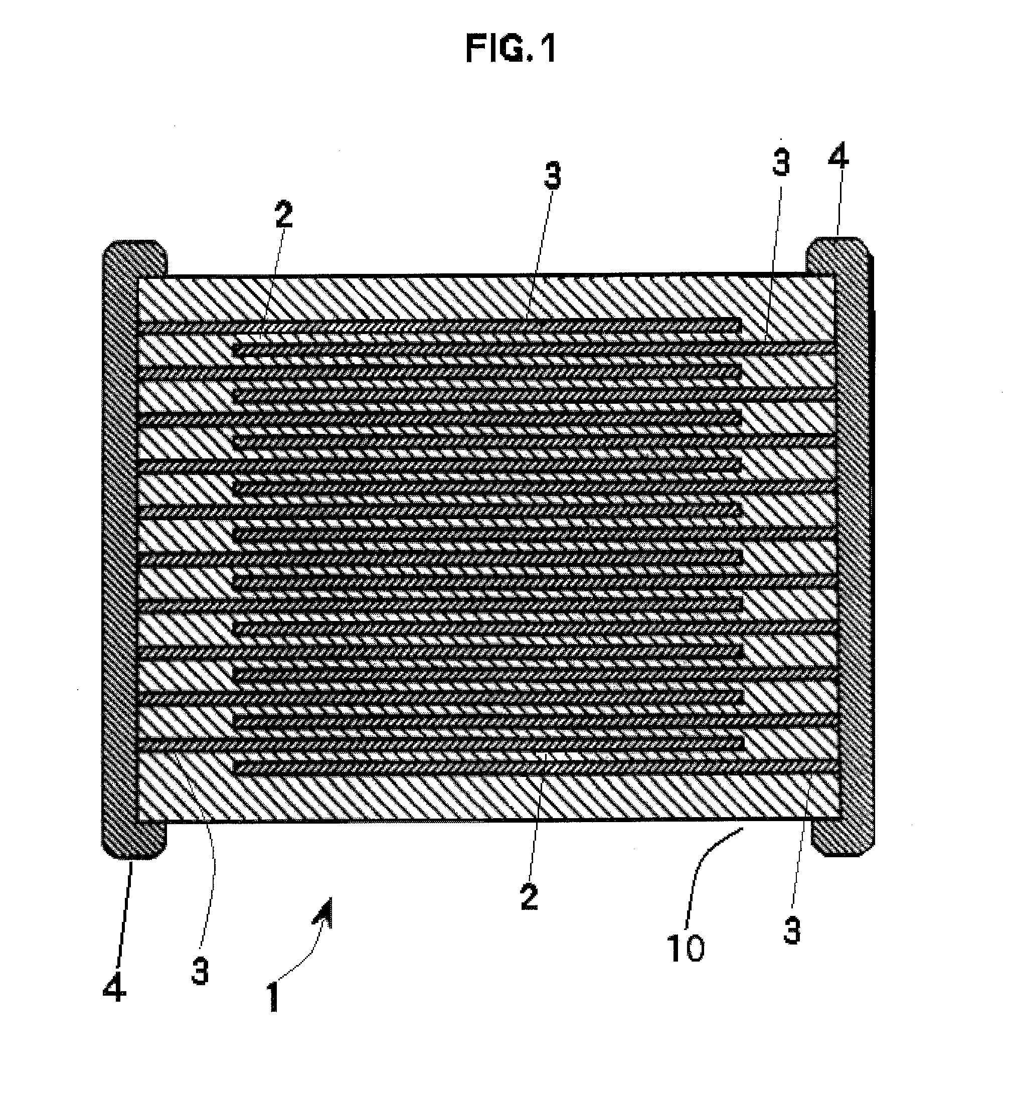
Firing in a reducing atmosphere, however, causes the dielectric layers to be reduced, which decreases resistivity.
Multilayer ceramic chip capacitors using non-reducible dielectric materials have been proposed, however, such devices typically have a shorter life of insulation resistance (IR) and low reliability.

Method used


Image

  • COG Dielectric Composition For Use With Nickel Electrodes
  • COG Dielectric Composition For Use With Nickel Electrodes

Examples


example 1

[0046]A dielectric composition identified as Sample 1 was formed by milling in water appropriate amounts of the oxides as shown in Table 4. The powders were milled in 1 liter polypropylene jar with 1% Darvan® C, a polymeric deflocculant available from RT Vanderbilt Co., Inc., Norwalk, Conn., using 2 mm YTZ (yttria stabilized zirconia) to a particle D50 of about 0.65 micron.

TABLE 4Formulation Of Sample 1 Prior To FiringSrZrO3SrTiO3CaTiO3Sr2Nb2O7Mg(OH)2H3BO3MnOWt %76.1862.9046.03213.5130.6340.6720.059

[0047]The dried powder was pulverized by conventional means to afford the dielectric powder of Example 1.

[0048]The final powders had an average particle size of 0.3 to 1 micron. One hundred grams of the above powders was then added to 28.8 grams of an organic vehicle comprising polyvinyl butanol, toluene, and ethanol, and wet milled for 24 hours to prepare a slurry for tape casting. The wet slurry was coated on a polyester film to form dielectric green tapes. The thickness of the dielectr...

example 2

[0051]A dielectric composition identified as Sample 2 was formed in the same manner as the dielectric composition identified in Example 1, with the formula as shown in Table 7.

TABLE 7Formulation Of Sample 2 Prior To FiringSrZrO3CaTiO3Sr2Nb2O7Nd2Zr2O7Mg(OH)2H3BO3MnOWt %71.3387.66312.6537.0640.5930.6290.060

[0052]Multilayer chip capacitors were made from the powders of Example 2 and tested. Firing conditions as well as electrical properties are summarized in Table 8.

TABLE 8Firing Conditions And Electrical Properties For MLCCs Of Example 2Sample  2Sintering Temp (° C.)1300Sintering Time (hours)  2pO2 (atm)  10−9Dielectric Thickness   13.7(microns)Capacitance (pF)  561.0DF (%)    0.045Dielectric Constant 45TCC (ppm / ° C.)−55° C. −6685° C. −78125° C. −80IR (1012 OHM)25° C.   7.3125° C.   6.6Breakdown Voltage (V)1589

example 3

[0053]A dielectric composition identified as Sample 3 was formed in the same manner as the dielectric composition identified in Example 1, with the formula as shown in Table 9.

TABLE 9Formulation Of Sample 3 Prior To FiringSrZrO3CaTiO3Sr2Nb2O7Nd2Zr2O7SrCO3TiO2Mg(OH)2H3BO3MnOWt %78.7243.44211.5802.7711.0111.5050.4550.4840.028

[0054]Multilayer chip capacitors were made from the powders of Example 3 and tested. Under identical firing conditions of dielectric compositions in Examples 1 and 2 did not densify and were unable to be tested electrically.


PUM

PropertyMeasurementUnit
dielectric constantaaaaaaaaaa
temperatureaaaaaaaaaa
pressureaaaaaaaaaa

Abstract

Multilayer ceramic chip capacitors which satisfy COG requirements and which are compatible with reducing atmosphere sintering conditions so that non-noble metals such as nickel and nickel alloys may be used for internal and external electrodes are disclosed. The capacitors exhibit desirable dielectric properties (high capacitance, low dissipation factor, high insulation resistance), excellent performance on highly accelerated life testing, and very good resistance to dielectric breakdown. The dielectric layers comprise a strontium zirconate matrix doped with other metal oxides such as TiO2, MgO, B2O3, CaO, MnO, Nd2O3 and Nb2O5 in various combinations.

Description

BACKGROUND OF THE INVENTION[0001]1. Field of Invention[0002]This invention relates to a zirconate titanate based dielectric composition, and more particularly to a doped strontium-zirconate based dielectric composition that can be used to form multilayer ceramic chip capacitors having internal base metal electrodes formed of nickel or nickel alloys.[0003]2. Description of Related Art[0004]Multilayer ceramic chip capacitors have been widely utilized as miniature-sized, high capacitance and high reliability electronic components. In accordance with increasing demands for high-performance electronic equipment, multilayer ceramic chip capacitors also have encountered marketplace demand for smaller size, higher capacitance, lower cost, and higher reliability.[0005]Multilayer ceramic chip capacitors generally are fabricated by forming alternating layers of an internal electrode forming paste and a dielectric layer-forming paste. Such layers are typically formed by sheeting, printing, or s...

Claims


Application Information

Patent Timeline
Patent Type & Authority Applications(United States)
IPC IPC(8): H01G4/12H01G4/01H01G4/008C04B35/491H01G4/30
CPCC04B35/486H01G4/1236H01G4/12B32B18/00C04B35/6261C04B2235/3206C04B2235/3208C04B2235/3213C04B2235/3224C04B2235/3232C04B2235/3236C04B2235/3244C04B2235/3248C04B2235/3251C04B2235/3255C04B2235/3262C04B2235/3409C04B2235/5445C04B2235/6025C04B2235/6582C04B2235/6584C04B2235/6588C04B2237/348C04B2237/68H01G4/01H01G4/0085C04B35/491H01G4/1245H01G4/30C04B35/49
Inventor SYMES, JR., WALTER J.
Owner FERRO CORP
Why Eureka
Try Eureka