Organic electroluminescent device, method of preparing same, display substrate, and display apparatus

a technology of electroluminescent devices and substrates, applied in the field of display products, can solve the problems of short life, low luminescence efficiency, and occurrence of self-quenching

Active Publication Date: 2016-10-13
BOE TECH GRP CO LTD
View PDF0 Cites 16 Cited by
  • Summary
  • Abstract
  • Description
  • Claims
  • Application Information

AI Technical Summary

Benefits of technology

[0045]The present invention produces advantageous effects including: the agglomeration and self quenching of quantum dots can be effectively prevented as the quantum dots are uniformly dispersed in the electroluminescent polymer fibers according to the invention; a relatively high quantum yield can be achieved by the fluorescence resonance energy transfer effect between the electroluminescent polymer and the quantum dots, and the luminescence efficiency of the quantum dots can be improved. Moreover, since the light emission from quantum dots is achieved by the fluorescence resonance energy transfer effect (which is an energy transfer process without damage to the quantum dots), the damage to quantum dots per se is less and thus the lifetime thereof is beneficially increased, as compared to the direct charge injection mode of the prior art.
[0046]The features or elements of the respective aspects and embodiments of the present invention described herein can be combined with each other. Unless indicated otherwise, all the numbers expressing the sizes of elements, quantities of ingredients and measurement of properties used herein are to be understood as being modified in all instances by the term “about”. Accordingly, unless indicated to the contrary, the numerical parameters set forth in the specification and attached claims are approximations that can vary depending upon the desired properties sought to be obtained by those skilled in the art utilizing the teachings of the present invention. In addition, unless indicated otherwise, the recitation of numerical ranges by endpoints includes the endpoints, as well as all subsets and numbers subsumed within that range (e.g., 1%-5% includes 1%, 3%, 5%, 2-4%, etc.). As used herein, the term “and / or” means any one, or more, or even all of the options listed can be chosen.
[0047]The present invention will be explained in further detail with reference to the preferred embodiments.
[0048]In one embodiment, OEL devices as shown in FIG. 1 were provided. The OEL devices were respectively produced by a process comprising the following steps.
[0049]1. Preparation of an anode, a hole injection layer, and a hole transport layer
[0050]On a glass substrate 1, an anode 2, a hole injection layer 3 and a hole transport layer 4 were prepared according to a process of the prior art. For more details of the process, see Colvin V L, Schlamp M C, and Alivisatos A P, Light-emitting diodes made from cadmium selenide nanocrystals and nanocrystals and a semiconducting polymer, Nature, 1994, 370(4): 354-357.

Problems solved by technology

However, there are still some problems in the QD-LED display apparatus of the prior art, including, for example,1. the occurrence of self quenching, low luminescence efficiency, short life, and other problems caused by the tendency of quantum dots to agglomerate with each other;2. the occurrence of damages and decreased lifetime caused by ionization of quantum dots, as the excitons generated by the quantum dots in the charge injection mode are prone to Auger recombination; and3. the occurrence of changes in the physicochemical properties of the quantum dots per se caused by the injection of a large amount of charges (such as oxidation or reduction effect).

Method used


Image

  • Organic electroluminescent device, method of preparing same, display substrate, and display apparatus
  • Organic electroluminescent device, method of preparing same, display substrate, and display apparatus
  • Organic electroluminescent device, method of preparing same, display substrate, and display apparatus

Examples


Embodiment Construction

[0020]The present invention is now described in more detail by way of certain embodiments with reference to the accompanying figures. The embodiments herein are intended to illustrate the present invention so that a person skilled in the art can get a better understanding of the invention, but the details thereof should not be construed as limiting the invention.

[0021]The method of preparing an OEL device according to the present invention comprises the following steps:

[0022]mixing an organic solvent, a charge control agent, an electroluminescent polymer and quantum dots homogeneously to obtain an electrostatic spinning solution; and

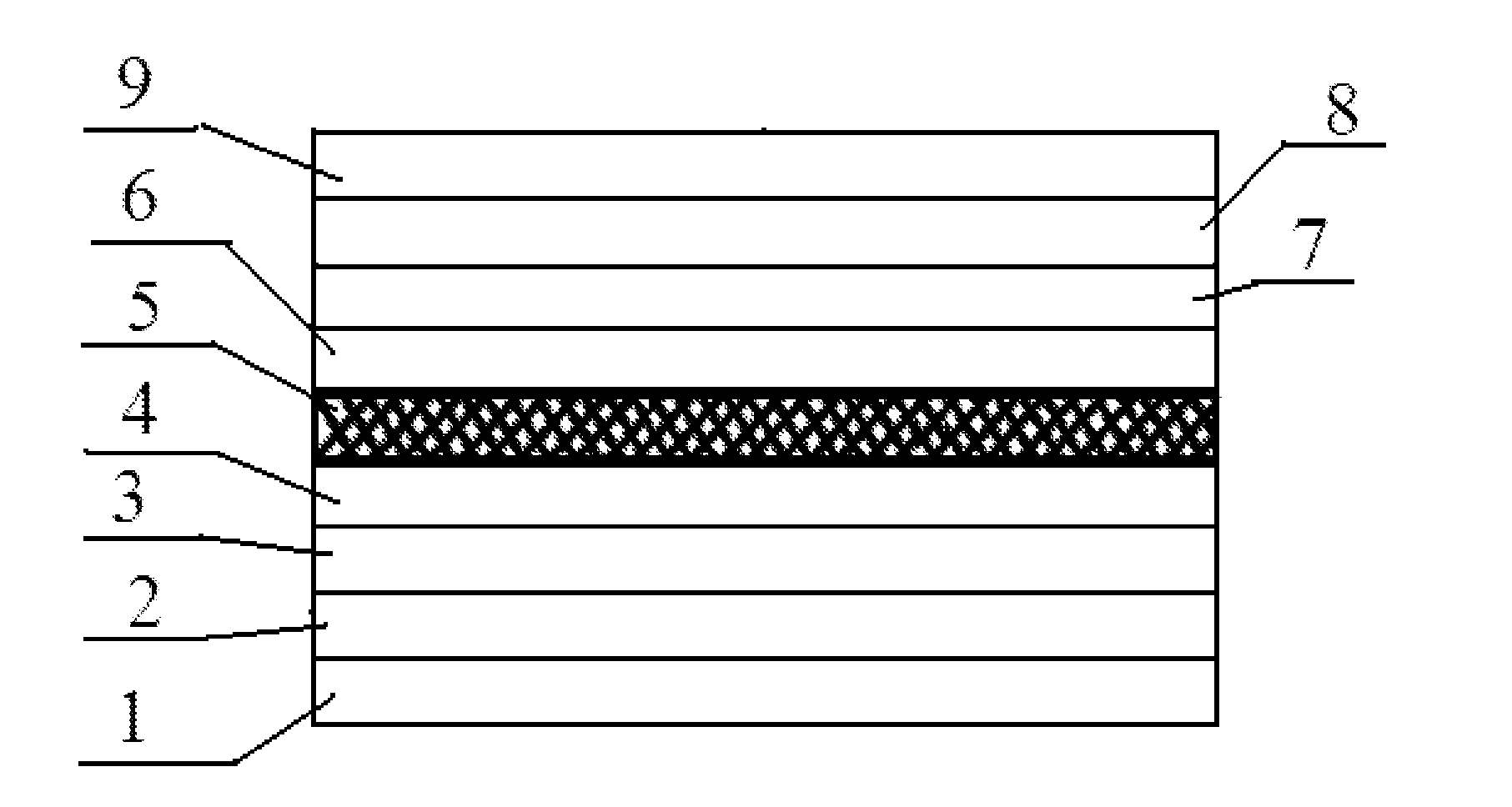
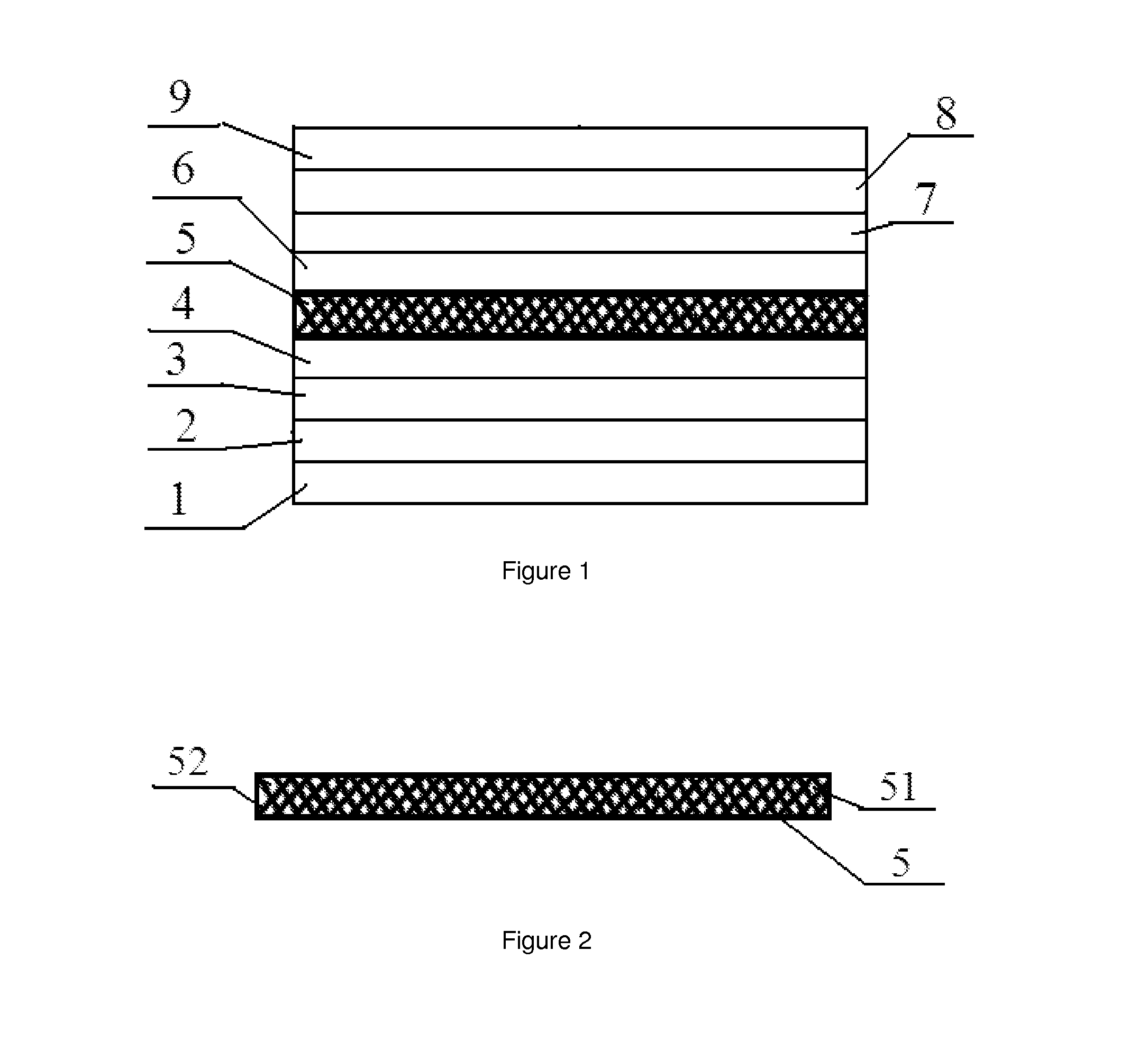
[0023]forming the electrostatic spinning solution into a quantum dot-containing OEL film by an electrostatic spinning process, wherein the quantum dot-containing OEL film is formed from fibers of the electroluminescent polymer dispersed with the quantum dots (as shown in FIGS. 1 and 2).

[0024]The organic solvent is useful for dissolving the charge control...


PUM

PropertyMeasurementUnit
boiling pointaaaaaaaaaa
temperatureaaaaaaaaaa
boiling pointaaaaaaaaaa

Abstract

This invention provides an organic electroluminescent device, a method of preparing the same, a display substrate comprising the same, and a display apparatus. According to the invention, the agglomeration and self quenching of quantum dots can be effectively prevented as the quantum dots are uniformly dispersed in electroluminescent polymer fibers. Due to the fluorescence resonance energy transfer effect between the electroluminescent polymer and the quantum dots, a higher quantum yield is achieved, and the luminescence efficiency of the quantum dots can be improved accordingly. Furthermore, since the light emission from the quantum dots is achieved by the fluorescence resonance energy transfer effect, which is an energy transfer process without damage to the quantum dots, the damage to quantum dots is less and thus the lifetime thereof can be beneficially increased, as compared to the direct charge injection mode of the prior art.

Description

FIELD OF THE INVENTION[0001]The present invention relates to the field of manufacturing of display products, and particularly to an organic electroluminescent (OEL) device, a method of preparing the OEL device, a display substrate comprising the OEL device, and a display apparatus comprising the display substrate.BACKGROUND OF THE INVENTION[0002]Quantum dot light-emitting diode (QD-LED) display is a new display technology developed on the basis of organic light-emitting display (OLED) and differs in the electroluminescent structure comprising a quantum dot layer.[0003]The electroluminescent structure of the existing QD-LED display comprises an anode, a hole injection layer, a hole transport layer, a quantum dot layer, a hole blocking layer, an electron transport layer, an electron injection layer, and a cathode, wherein electrons from the cathode are injected into the quantum dot layer through the electron injection layer, the electron transport layer and the hole blocking layer, wh...

Claims


Application Information

Patent Timeline
Patent Type & Authority Applications(United States)
IPC IPC(8): H01L51/50H01L51/00H01L51/56
CPCH01L51/502H01L51/56H01L51/5056H01L51/5096H01L51/0039H01L51/5092H01L51/5088H01L51/0007H01L2251/558H01L51/5072H10K50/115H10K71/00H10K71/15H10K85/115H10K50/15H10K50/16H10K50/17H10K50/18H10K50/171H10K2102/351
Inventor HE, XIAOLONGCAO, ZHANFENGYAO, QI
Owner BOE TECH GRP CO LTD
Why Eureka
Try Eureka