Machine to detect Phonon Gain to Control Desired Reactions in an Electrically Driven Hydrogen Loaded Material

a technology of phonon gain and desired reaction, which is applied in the direction of nuclear engineering, greenhouse gas reduction, nuclear reactors, etc., can solve the problems of not being true, no single error or combination of errors on the part of all scientists can explain the development, and the occurrence of nuclear reactions in deuterium-loaded solids such as palladium and titanium cannot be reasonably denied. , to achieve the effect of improving the visualization of undesired reactions

Inactive Publication Date: 2016-11-10
SWARTZ MITCHELL R
View PDF1 Cites 4 Cited by
  • Summary
  • Abstract
  • Description
  • Claims
  • Application Information

AI Technical Summary

Benefits of technology

[0128]The invention described by the above-entitled application thus solves the problem of permitting easy, real time, visualization of the requisite state of the material as to both the desired reactions and undesired states, features of great utility.
[0129]The present invention can also be...

Problems solved by technology

However, this is not true.
In addition, many US agencies such as DTRA, DARPA, DIA, the US Navy, and hundreds of scientists disagree with any such false notions.
The occurrence of nuclear reactions in deuterium-loaded solids, such as palladium and titanium can no longer be reasonably denied.
No single error or combination of errors on the part of all of the scientists can explain the developing results.
First, not all emission branches from the excited state of He4* are even spin-available.
In LANR, given the actual much smaller amount of thermal energy, kB*T, available for cold fusion (˜ 1/25 eV), absence of adequate activation energy decisively means that that branch is NOT available, as it is for hot fusion.
Second, the relative absence of neutron and hard gamma-ray penetrating radiation in cold fusion appears to be also due to the lack of availability of adequate temperature for two different, and thermally linked, reasons (Swartz 13, 23).
Insufficient current densities are subthreshold for the desired reactions, and when the voltage becomes too high, then undesirable low dielectric constant layers (large bubble gases) develop in front of the cathode.
The problem is that electrical current alone does not, and cannot, reflect the quantity of deuterons entering the palladium lattice (related to the loading flux).
Furthermore, during the reactions, the system may not even be at equilibrium.
The LANR method which P-F first taught in March 1989 (hereinafter “F+P”) had problems, including inefficiency, non-reproducibility, and a requirement for very high loading and long incubation time.
One major problem has been the difficulty in achieving high D/Pd loadings above ˜0.70 near room temperature—and maintaining that for weeks.
This was a major problem in early LANR replication because until the early 1990s special effort was not made to achieve high loading required.
Driving with electrical input power beyond the peak optimal operating point does not improve the pro...

Method used


Image

  • Machine to detect Phonon Gain to Control Desired Reactions in an Electrically Driven Hydrogen Loaded Material
  • Machine to detect Phonon Gain to Control Desired Reactions in an Electrically Driven Hydrogen Loaded Material
  • Machine to detect Phonon Gain to Control Desired Reactions in an Electrically Driven Hydrogen Loaded Material

Examples


Embodiment Construction

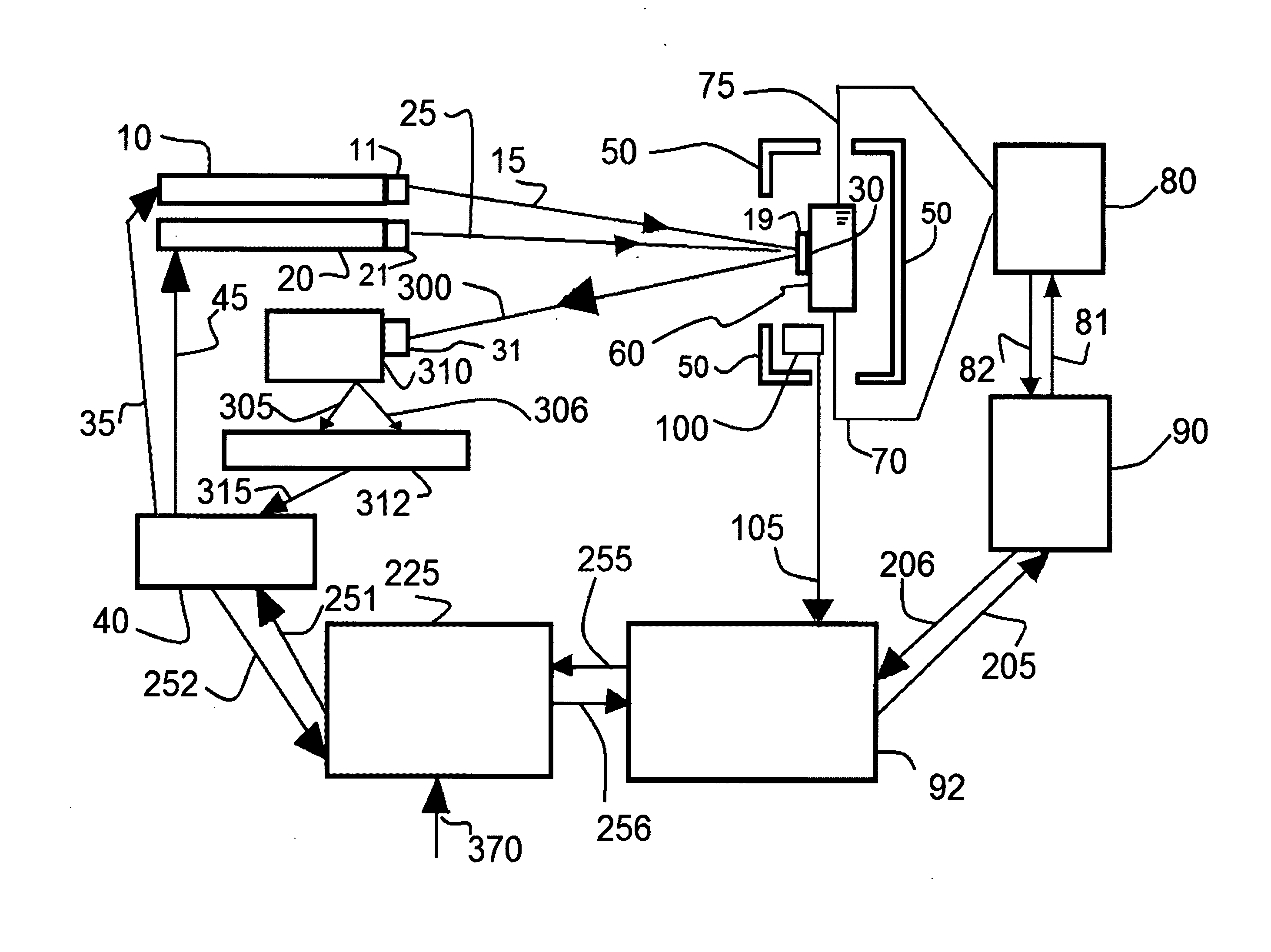
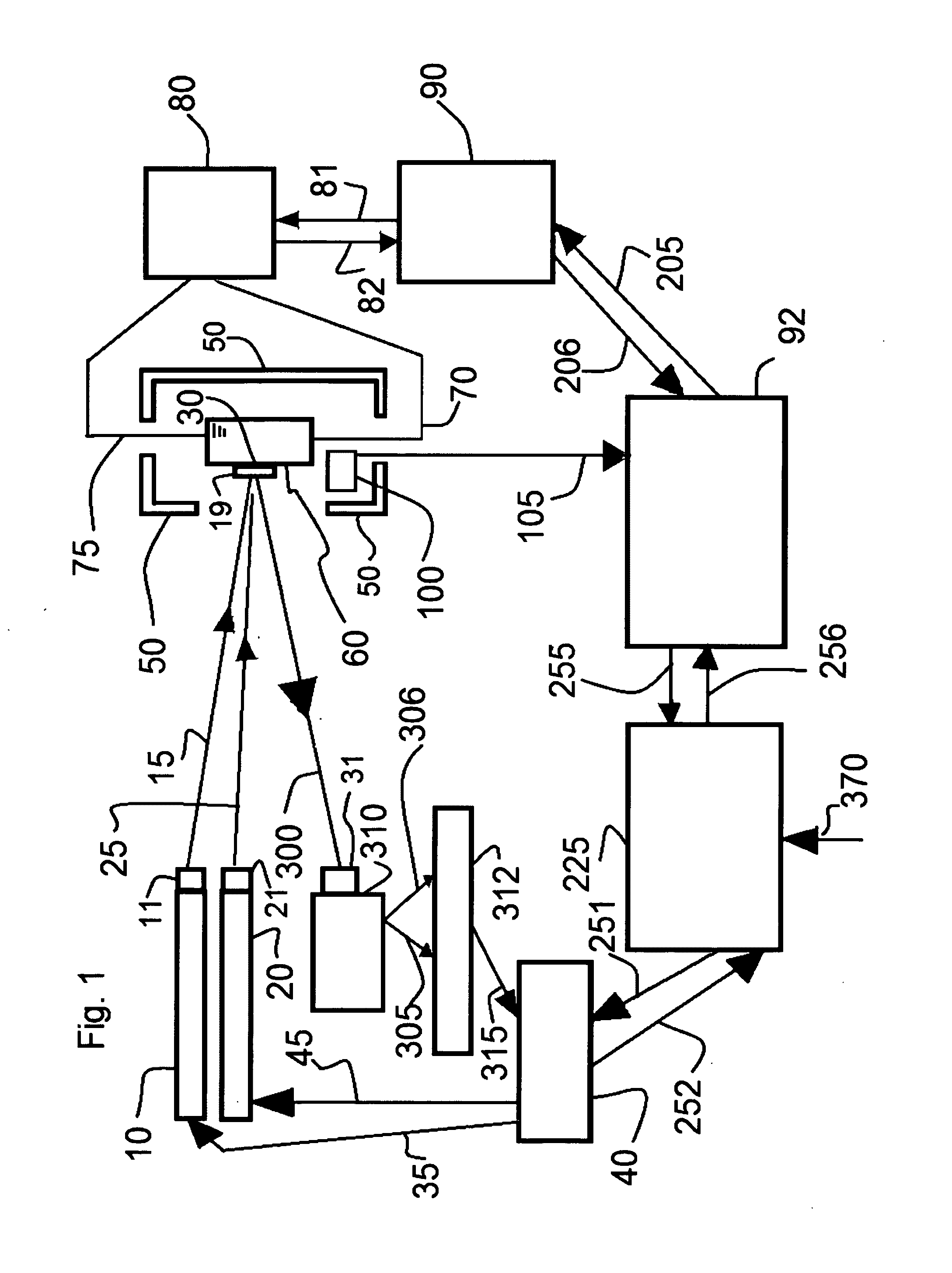
[0147]The detailed summary will now be explained through the claims, and figures and original specification. Turning now to the figures. In accordance with the teachings of the present invention, FIG. 1 shows a schematic block diagram of the above entitled invention which lists the subunits, and significant control points of light, energy, information and electrical flow. Shown are two lasers (labeled number 10 and number 20) which are capable of illuminating a target (labeled 30) which is located on the surface of a sample of interest (labeled 60).

[0148]The lasers produce two optical beams of coherent radiation (labeled 15 and 25). Optics for collimation, beam direction, band pass, and the like are shown, and labeled as 11 and 21. Those two optical beams overlap, and as a control do not, at the sample's surface, at a chosen target location (labeled 30) and, at a location where thereafter they interact with said sample (60). A geometric lens, and the like, (labeled 19) optionally ca...


PUM


Abstract

A machine to detect phonon gain to control desired reactions using a container with at least two optical ports, a power supply and wiring connections to enable driving a material sample to be examined, a power supply to drive at least two lasers, a controller to regulate the output of the lasers, a beam path to enable illumination of the sample, a controller to regulate the electric power delivered to the sample enabling driving in more than one state, a detector system to examine the backscatter radiation from the sample by frequency, a second beam path to enable the backscatter to reach the detector system, a computation system to separate and determine the ratios of the examined backscattered frequencies to determine the intensities and distribution, and a second computation system to compare the examined intensities and distribution and ratios to the desired intensities and distribution and ratios to determine what states were detected and to derive changes for the power supply driving the sample.

Description

CROSS REFERENCE TO RELATED APPLICATIONS[0001]This is a Continuation-in-part of Ser. No. 07 / 339,976 Filed: Apr. 18, 1989STATEMENT REGARDING FEDERALLY SPONSORED RESEARCH OR DEVELOPMENT[0002]Not ApplicableDESCRIPTION OF ATTACHED APPENDIX[0003]Peer-reviewed publications as Exhibits attesting to Operability, Utility and the likeOTHER PATENTS AND PUBLICATIONS[0004]By way of background and to place reasonable limits on the size of this disclosure, the following references and articles may be used by way of background material and to supplement this specification. Because reference is made to the following articles with a description of patterns of failure and their relation to loading, materials, methods, and terms discussed below, which may be employed in the discussion and claims of the present application, the cited references are incorporated as if included herein.[0005]1. Swartz, M. P. Hagelstein, G. Verner, Impact of Electrical Avalanche Through a ZrO2-NiD Nanostructured CF / LANR Comp...

Claims


Application Information

Patent Timeline
IPC IPC(8): G21D3/08G21D7/00G21B3/00
CPCG21D3/08G21D7/00G21B3/00G21B3/002Y02E30/10
Inventor SWARTZ, MITCHELL R.
Owner SWARTZ MITCHELL R
Why Eureka
Try Eureka