Magnetic core and coil component using same

a technology of magnetic core and coil component, applied in the field of magnetic core, can solve the problems of low specificity, difficult high-frequency application of magnetic core, inferior strength, etc., and achieve the effects of excellent specific resistance, strength and rust prevention, and easy compacting and heat treatmen

Active Publication Date: 2016-11-17
HITACHI METALS LTD
View PDF4 Cites 18 Cited by
  • Summary
  • Abstract
  • Description
  • Claims
  • Application Information

AI Technical Summary

Benefits of technology

[0022]According to the present invention, there can be provided a magnetic core which is excellent in specific resistance, strength and rust prevention and which is easily compacted and heat-treated and is excellent in productivity; and a coil component using the magnetic core.

Problems solved by technology

On the other hand, since such a magnetic core contains a large amount of Fe, and therefore easily gets rusty, and also has a low specific resistance and a large eddy current loss, the magnetic core is considered to be difficult to use in high-frequency applications with a frequency of more than 100 kHz unless the alloy particles are coated with an insulating material such as resin and glass.
Accordingly, Fe-based magnetic alloy particles are bonded together via the insulating material, and therefore may be inferior in strength as compared to ferrite magnetic cores because the strength of the magnetic core is affected by the strength of the insulating material.

Method used


Image

  • Magnetic core and coil component using same
  • Magnetic core and coil component using same
  • Magnetic core and coil component using same

Examples


examples

[0069]Examples of the present invention will now be described in detail.

[0070](1) Preparation of Fe-Based Soft Magnetic Alloy Particles

[0071]First, an ingot was prepared using elemental raw materials of Fe, Al, Cr and Si each having a purity of more than 99.9%. In this example, high-purity raw materials were intentionally used for controlling the impurity level of Si. The prepared ingot was melted in a high-frequency induction furnace, and powdered by a water atomization method to obtain Fe-based soft magnetic alloy particles. The contents of C, Mn, P and S as impurities contained in the ingot were determined, and the result showed that they were each less than 0.05% by mass. Natural oxide films formed on the surfaces of the alloy particles were identified by Auger electron spectroscopy (JAMP-7830F manufactured by JEOL Ltd.). The results are shown in Table 1. Table 1 also shows the results of composition analysis of Fe-based soft magnetic alloy particles. The analysis values were va...

working examples 5 to 9

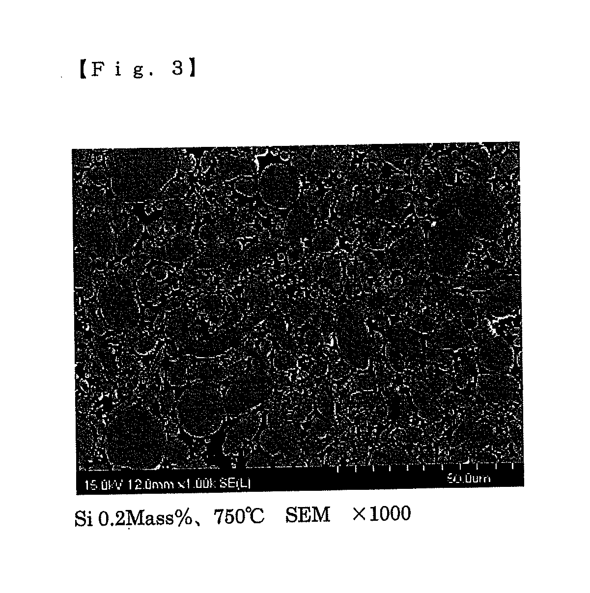
[0132]Magnetic cores having different composition amounts of Si in Fe-based soft magnetic alloy particles were prepared. For the magnetic cores, Fe-based soft magnetic alloy particles of alloys Nos. 2 to 6 in Table 1 were used. Alloy particles were formed by the granulation method 1, then filled into a die, pressed at a pressure of 0.74 GPa, and heat-treated in the air at an annealing temperature of 750° C. with a holding time of 1 hour to obtain a magnetic core. The characteristics, such as the specific resistance and the radial crushing strength, of the obtained magnetic core were evaluated. The results are shown in Tables 9 and 10.

TABLE 9DensityCompactafterRadialAmountdensity annealing SpaceSpecificcrushingAlloyof Sidg × 103 dg × 103 factorresistance × 103 strengthNo.(% by mass)(kg / m3)(kg / m3)(%)Ω· m at 50 V(MPa)Working20.116.216.4588.614.0244Example 5Working10.206.076.3687.411.0287Example 3Working30.306.206.3787.619.0217Example 6Working40.47Not-measured6.3687.57.0219Example 7Work...

working examples 10 and 11

[0137]Magnetic cores having different composition amounts of Cr and Al in Fe-based soft magnetic alloy particles were prepared. For the magnetic cores, Fe-based soft magnetic alloy particles of alloys Nos. 7 and 8 in Table 1 were used. Alloy particles were formed by the granulation method 1, then filled into a die, pressed at a pressure of 0.74 GPa, and heat-treated in the air at an annealing temperature of 750° C. with a holding time of 1 hour to obtain a magnetic core. The characteristics, such as the specific resistance and the radial crushing strength, of the obtained magnetic core were evaluated. The results are shown in Tables 12 and 13.

TABLE 12DensityCompactafterSpecificRadialdensity dg ×annealingSpaceresistance ×crushing103dg × 103factor103 Ω· mstrength(kg / m3)(kg / m3)(%)at 50 V(MPa)Working6.16.3287.13227Example 10WorkingNot-6.0985.521.0217Example 11evaluated

TABLE 13Abundanceratio ofalloyparticlesIncre-havingAverageMagnetic core mental maximumofloss (kW / m3)perme-diameter of ma...


PUM

PropertyMeasurementUnit
saturation magnetic flux densityaaaaaaaaaa
frequencyaaaaaaaaaa
temperatureaaaaaaaaaa

Abstract

A magnetic core has a structure in which Fe-based soft magnetic alloy particles are connected via a grain boundary. The Fe-based soft magnetic alloy particles contain Al, Cr and Si. An oxide layer containing at least Fe, Al, Cr and Si is formed at the grain boundary that connects the neighboring Fe-based soft magnetic alloy particles. The oxide layer contains an amount of Al larger than that in Fe-based soft magnetic alloy particles, and includes a first region in which the ratio of Al is higher than the ratio of each of Fe, Cr and Si to the sum of Fe, Cr, Al and Si, and a second region in which the ratio of Fe is higher than the ratio of each of Al, Cr and Si to the sum of Fe, Cr, Al and Si. The first region is on the Fe-based soft magnetic alloy particle side.

Description

TECHNICAL FIELD[0001]The present invention relates to a magnetic core formed by Fe-based soft magnetic alloy particles, and a coil component with a wire wound around the magnetic core.BACKGROUND ART[0002]Hitherto, coil components such as an inductor, a transformer, and a choke coil, have been used in various articles such as household electric appliances, industrial equipment, and vehicles. A coil component includes a magnetic core and a coil wound around the magnetic core. In this magnetic core, ferrite, which is excellent in magnetic property, shape flexibility and costs, has widely been used.[0003]In recent years, a decrease in the size of power source devices of electronic instruments and others has been advancing, so that intense desires have been increased for coil components which are small in size and height, and are usable against a large current. As a result, the adoption of powder magnetic cores, in each of which a metallic magnetic powder is used, and which are higher in...

Claims


Application Information

Patent Timeline
Patent Type & Authority Applications(United States)
IPC IPC(8): H01F27/255C22C38/08C22C38/06C22C38/04C22C38/02H01F27/28B22F9/08B22F1/00B22F9/04B22F3/24B22F3/04B22F3/03C22C38/18C22C38/00B22F1/052B22F1/08B22F1/102B22F1/16
CPCH01F27/255B22F2003/248C22C38/08C22C38/06C22C38/04C22C38/02C22C38/002C22C38/001B22F9/082B22F1/0062B22F9/04B22F3/24B22F3/04B22F3/03H01F27/2823B22F2009/0828C22C38/18C22C33/02C22C38/00C22C45/02H01F1/24H01F1/33H01F41/0246C22C33/0257C22C33/0264B22F2998/10B22F2999/00B22F1/052B22F1/102B22F1/16B22F1/08B22F5/10B22F2207/07C22C2202/02B22F1/10B22F2009/0824B22F1/148B22F2003/023B22F3/14H01F1/12H01F1/14766H01F1/14791H01F27/28B22F3/02
Inventor NOGUCHI, SHINNISHIMURA, KAZUNORIMIHARA, TOSHIO
Owner HITACHI METALS LTD
Why Eureka
Try Eureka