Photoelectrochemical devices, methods, and systems with a cupric oxide/cuprous oxide coated electrode

a technology of cupric oxide and photoelectrochemical devices, which is applied in the direction of catalyst activation/preparation, metal/metal-oxide/metal-hydroxide catalysts, energy input, etc., can solve the problems of large carbon footprint of hydrocarbon based products, finite reserves, and presence of fossil fuels, so as to achieve energy efficiency and/or cost efficiency, the effect of reducing the toxicity

Active Publication Date: 2016-12-01
BOARD OF RGT THE UNIV OF TEXAS SYST
View PDF0 Cites 8 Cited by
  • Summary
  • Abstract
  • Description
  • Claims
  • Application Information

AI Technical Summary

Benefits of technology

[0006]The present application offers a solution to the current problems associated with generating alcohols, such as methanol, ethanol, and propanol, with CO2 in an energy efficient and / or cost efficient manner, especially one with lower toxicity. The solution is premised on a photoelectrochemical device comprising a photocathode having a CuO / Cu2O nanorod array. Photoelectrochemical cells in accordance with the present disclosure can be used to convert CO2 and water into one or more alcohols. With the use of a CuO / Cu2O nanoarray, a combination of solar energy and electricity can drive the reaction, and thus, it is referred to as a “photoelectrochemical” (PEC) process. The devices, systems, and methods in accordance with the present invention can be used to produce reaction products, like CO2, on a continuous basis.

Problems solved by technology

Despite their wide application and high demand, fossil fuels present a number of disadvantages, including the finite reserve, irreversible combustion and contribution to air pollution and global warming.
However, the current feedstock for this production is hydrocarbon based with a sizeable carbon footprint.
Further, the high operating pressures and temperatures needed for steam reforming translate into correspondingly high capital investment and a long energy pay-back period.

Method used


Image

  • Photoelectrochemical devices, methods, and systems with a cupric oxide/cuprous oxide coated electrode
  • Photoelectrochemical devices, methods, and systems with a cupric oxide/cuprous oxide coated electrode
  • Photoelectrochemical devices, methods, and systems with a cupric oxide/cuprous oxide coated electrode

Examples


example 1

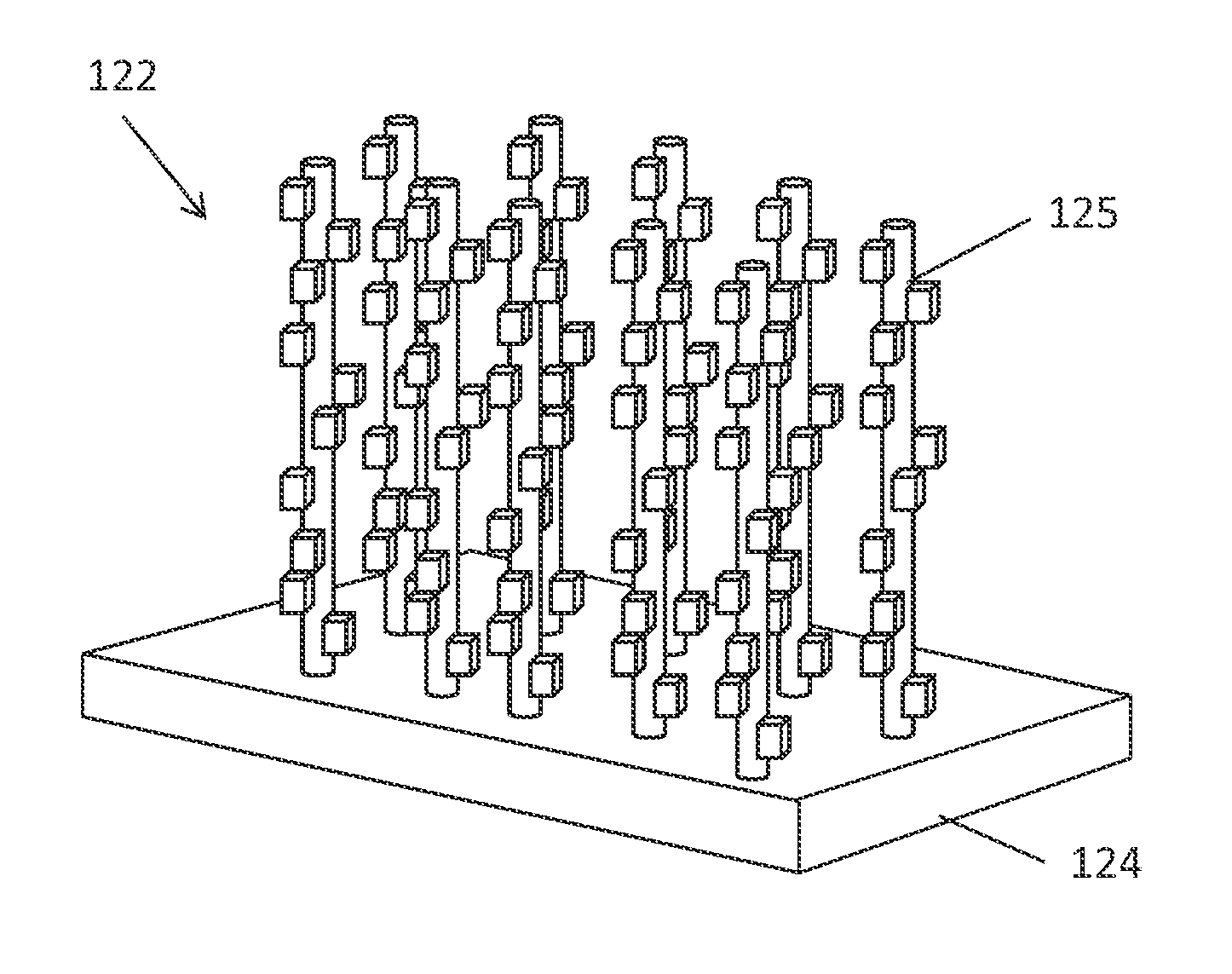
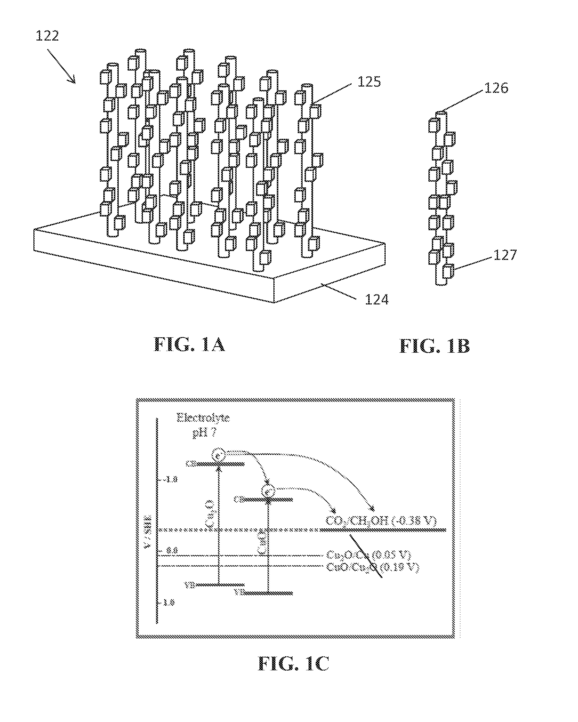
Preparation of a CuO & Cu2O Nanorod Array Photocathode by a Thermal Procedure to Form CuO Array

[0083]In the first step of preparing a nanorod array in accordance with the present disclosure, a CuO nanorod array was formed by a thermal procedure. Specifically, the CuO rods were grown on a copper foil substrate. First, Cu foil was cut to size and was cleaned by immersing in a 1.0M H2SO4 solution, then sonicated in isopropanol, acetone, and deionized water, respectively, and finally, dried under nitrogen gas.

[0084]Next, the CuO nanorods were then grown on the freshly cleaned Cu substrate by a thermal procedure in accordance with the reference: X. Jiang, T. Herricks, and Y. Xia, Nano Letters, 2002, 2, 1333, which is hereby incorporated by reference in its entirety. The copper foil was isothermally heated at 400° C. for 4 hours. A temperature program was used and comprised first heating the sample up to 400° C. (at 25° C. / min). After 4 hours of isothermal heating, the sample was allowed ...

example 2

Preparation of a CuO & Cu2O Nanorod Array Photocathode

[0092]The CuO / Cu2O nanorod arrays were fabricated by a two-step process performed on freshly cleaned copper as described in Example 1. However, this procedure deviates from Example 1. In the first step, freshly cleaned Cu substrates were immersed in the mix solution 8.0 mL of the NaOH solution (10 M), 4.0 mL of a (NH4)2S2O8 solution (1.0 M), and 18.0 mL of water. A few minutes later, a blue color appeared on the copper foil surface, and the solution became increasingly blue. In 15 minutes, a light-blue film covered the copper foil surface. The copper foil was taken out of the solution, rinsed with water, and dried in air. The Cu(OH)2 fibers and scrolls were converted CuO by thermal oxidation in presence of air using a box furnace for 1 h. at 200° C. (at 25° / min.), the temperature was allowed to return naturally to room temperature. Longer soaking times in the solution were also performed (50 min. and 80 min.) and produced the den...

example 3

Converting CO2 to Methanol with the Photocathode

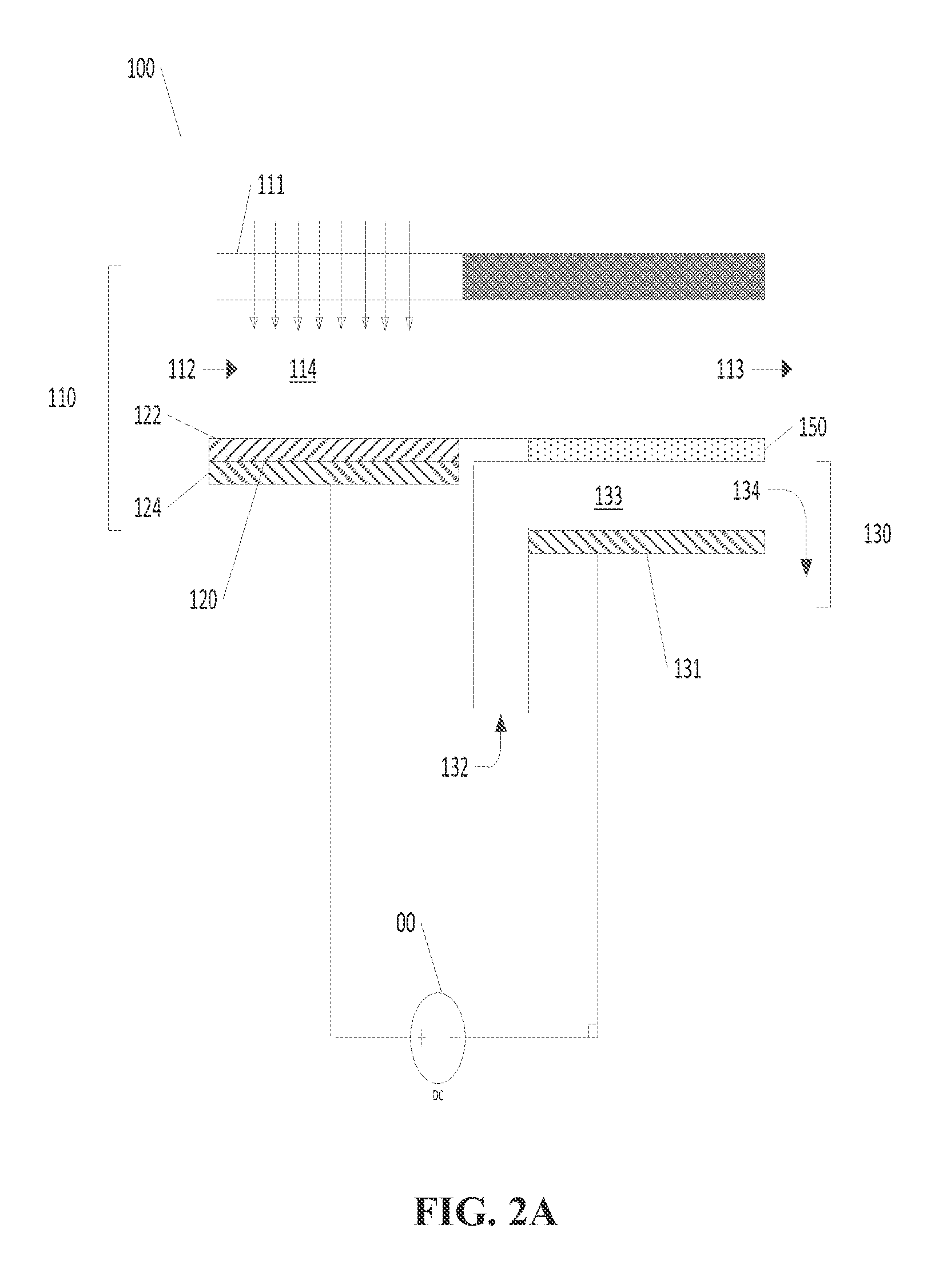
[0094]Photoelectrosynthesis of CH3OH was demonstrated with a TH / ED10 CuO / Cu2O nanorod photoelectrode. A Pt foil and an Ag / AgCl (satd. KCl) were used as the anode and reference electrode respectively.

[0095]The photoelectrode was placed in 100 mL electrolyte solution saturated with CO2, polarized at −0.2 V vs. SHE, and continually irradiated with visible light provided by a AM1.5 solar simulator. The irradiated electrode area was approximately 3 cm2. Representative photocurrent / time and charge / time profiles recorded during the photoelectrolysis are shown in FIGS. 10A and 10B respectively. To analyze the photoelectrogenerated product, liquid samples were periodically withdrawn from the photoelectrochemical cell. A gas chromatograph equipped with a mass spectrometer (GC-MS) was used to detect methanol. Methanol photogeneration was monitored at m / z=31 (CH2OH+) and was found to reach a concentration of approximately 85 μM after 90 min. of ir...


PUM

PropertyMeasurementUnit
widthaaaaaaaaaa
widthaaaaaaaaaa
lengthaaaaaaaaaa

Abstract

The present disclosure relates to nanocomposites of CuO/Cu2O and continuous flow solar reactors. The nanocomposites can be utilized as a photocatalyst and can be incorporated into photoelectrochemical devices. The described devices, systems, and methods can be used for converting CO2 into one or more alcohols and other small organics with the use of solar energy and electricity. Other embodiments are described.

Description

CROSS-REFERENCE TO RELATED APPLICATIONS[0001]This application claims priority to United States Provisional Application No.: 61 / 928,700 filed Jan. 17, 2014. The entire text the above-referenced disclosure is specifically incorporated herein by reference without disclaimer.BACKGROUND OF THE INVENTIONField of the Invention[0002]The invention generally concerns methods, devices, and systems using an electrode having a CuO / Cu2O array as well as methods, devices, and systems related to continuous flow solar reactors.Description of Related Art[0003]Hydrocarbons are essential in modern life. Hydrocarbons are used as fuel and raw material in various fields, including the chemical, petrochemical, plastics, and rubber industries. Fossil fuels, such as coal, oil and gas, are composed of hydrocarbons with varying ratios of carbon and hydrogen, and are non-renewably used when combusted, forming carbon dioxide and water. Despite their wide application and high demand, fossil fuels present a number...

Claims


Application Information

Patent Timeline
Patent Type & Authority Applications(United States)
IPC IPC(8): C25B3/04C25B15/08C25B13/08C25B11/04H01G9/20C25B3/25
CPCC25B3/04C25B11/0478H01G9/2004C25B11/0415C25B11/0405C25B15/08C25B13/08B01J23/72B01J37/342B01J35/0013B01J35/002B01J35/0033B01J35/004B01J35/026B01D69/02B01D69/12B01D71/022B01D71/36B01D71/80B01D2325/10B01D2325/38B01D2325/42H01M14/005Y02E10/542Y02P20/133C25B3/25C25B11/057C25B11/051C25B11/091
Inventor DENNIS, BRIANRAJESHWAR, KRISHNANTACCONI, NORMACHANMANEE, WILAIWANHOMAYONI, HOMAYONGHADIMKHANI, GHAZALEH
Owner BOARD OF RGT THE UNIV OF TEXAS SYST
Why Eureka
Try Eureka