
Optical conversion member, method for manufacturing optical conversion member, backlight unit including optical conversion member, and liquid crystal display device

Active Publication Date: 2017-01-19
FUJIFILM CORP
View PDF1 Cites 15 Cited by
  • Summary
  • Abstract
  • Description
  • Claims
  • Application Information

AI Technical Summary

Benefits of technology

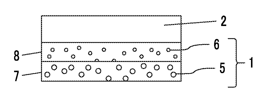
The present invention is about an optical conversion member that contains a quantum dot and has high light extraction efficiency. The invention solves the problem of light scattering to the back side, which causes an increase in re-absorption of the fluorescent light and decreases the light extraction efficiency. The invention provides an optical conversion member with a high light extraction efficiency that can be used in a backlight unit and a liquid crystal display device.

Problems solved by technology

However, as a result of studies of the present inventors with respect to the methods disclosed in US2012 / 0113672A1, it is found that the light extraction efficiency is not sufficiently enhanced, and a further increase in the light extraction efficiency is required.
However, recently, the method of increasing the light extraction efficiency has stagnated in each technical field.
As a result of intensive studies of the present inventors for attaining the object described above, it has been found that in a case where the light scattering of the fluorescent light from the quantum dot is performed by dispersing the particles as disclosed in US2012 / 0113672A1, a part of light in the waveguide mode repeating the total reflection is able to be extracted by scattering with respect to the front of the optical conversion member (the visible side), but a part of light which is able to be extracted scatters to the back side, and thus, a new problem occurs in which a distance (=an effective length of an optical path) in the matrix that the light scattering to the back side (a side opposite to the visible side) propagates before being extracted.

Method used


Image

  • Optical conversion member, method for manufacturing optical conversion member, backlight unit including optical conversion member, and liquid crystal display device
  • Optical conversion member, method for manufacturing optical conversion member, backlight unit including optical conversion member, and liquid crystal display device
  • Optical conversion member, method for manufacturing optical conversion member, backlight unit including optical conversion member, and liquid crystal display device

Examples


examples

[0301]Hereinafter, the characteristics of the present invention will be more specifically described with reference to examples. Materials, use amounts, ratios, treatment contents, treatment sequences, and the like of the following examples are able to be suitably changed unless the changes cause deviance from the gist of the present invention. Therefore, the range of the present invention will not be restrictively interpreted by the following specific examples.

examples 101 to 103

Preparation Method of Anisotropic Light Scattering Film: Preparation of Anisotropic Light Scattering Layer Formed by Photocuring Acrylate

1. Preparation of Anisotropic Light Scattering Film 11

[0302]11>

[0303]First, a photopolymerizable composition 1 (a coating liquid for an anisotropic diffusion layer) having the following compositions was applied onto a polyethylene phthalate (PET) film (Product Name: COSMOSHINE (Registered Trademark), Product Number: A4300, manufactured by TOYOBO CO., LTD.) having a thickness of 75 μm by using a doctor blade in which a gap was adjusted to be 0.2 mm, and then, was coated with another PET film (a thickness of 75 μm). The average refractive index of the used PET film was 1.60.

[0304]>

2-(Perfluorooctyl)-Ethyl Acrylate:50parts by mass1,9-Nonanediol Diacrylate:50parts by mass2-Hydroxy-2-Methyl-1-Phenyl Propan-1-One:4parts by mass

[0305]Next, a liquid film having a thickness of 200 μm (0.2 mm) in which both upper and lower surfaces were interposed between PE...

examples 105 and 106

4. Preparation of Barrier Layer Film

[0314]1 with Barrier Layer>

[0315]A photopolymerizable composition 2 (a barrier layer coating liquid) described below was prepared as a coating liquid, the coating liquid was applied onto a light exit side surface of the anisotropic light scattering film 11 prepared in 1. described above by using a wire bar of a wire bar (#6), an ultraviolet ray having irradiance of 350 mW / cm2 and irradiation dose of 500 mJ / cm2 was emitted by using an air-cooled metal halide lamp of 160 W / cm (manufactured by EYE GRAPHICS CO., LTD.) under nitrogen purge of an oxygen concentration of less than or equal to 0.1%, and thus, an organic layer having a film thickness of approximately 500 nm was formed.

[0316]>

Phosphoric Acid Ester Acrylate (KAYAMER10parts by massPM-21 manufactured by Nippon Kayaku Co., Ltd.);LIGHTACRYLATE BEPG-A manufactured by90parts by massKyoeisha Chemical Co., Ltd.;Photopolymerization initiator [IRGACURE9076parts by massmanufactured by BASF SE];

[0317]Fu...


PUM


Abstract

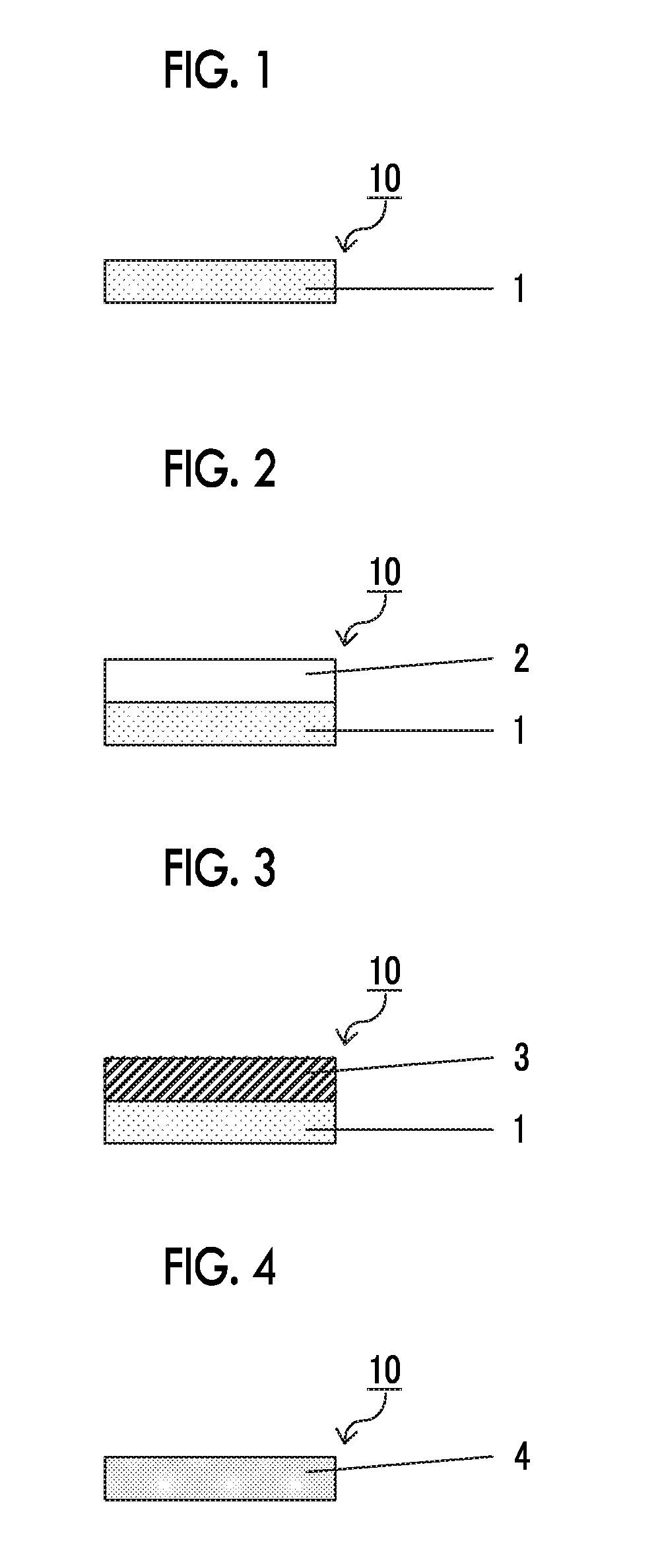
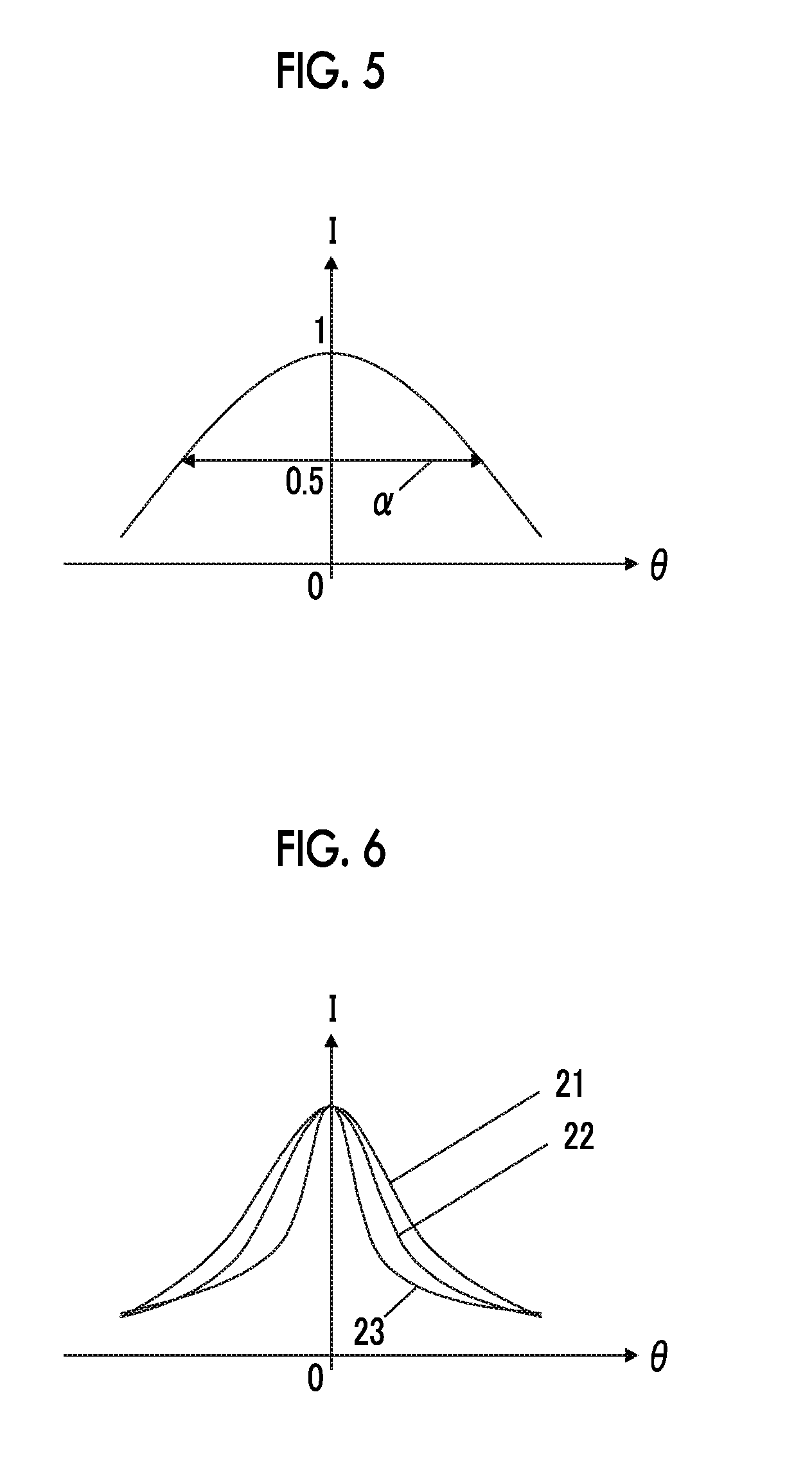
Disclosed is an optical conversion member, including an optical conversion layer containing quantum dot emitting fluorescent light and an anisotropic light scattering layer having I (0°) / I (40°) of 3 or greater, in which I (0°) indicates a transmission light intensity of the anisotropic light scattering layer at the time of allowing light to be incident on the anisotropic light scattering layer from a normal direction of a surface of the anisotropic light scattering layer, and I (40°) indicates a transmission light intensity of the anisotropic light scattering layer in an azimuth in which a transmission light intensity of the anisotropic light scattering layer at the time of allowing light to be incident on the anisotropic light scattering layer from a direction of a tilt angle of 40° with respect to the normal direction of the surface of the anisotropic light scattering layer becomes a minimum value.

Description

CROSS-REFERENCE TO RELATED APPLICATIONS[0001]This application is a Continuation of PCT International Application No. PCT / JP2015 / 059844, filed on Mar. 30, 2015, which claims priority under 35 U.S.C. Section 119(a) to Japanese Patent Application No. 2014-072034 filed on Mar. 31, 2014. Each of the above applications is hereby expressly incorporated by reference, in its entirety, into the present application.BACKGROUND OF THE INVENTION[0002]1. Field of the Invention[0003]The present invention relates to an optical conversion member (also referred to as a wavelength conversion member), and specifically, relates to an optical conversion member which contains a quantum dot and has a high light extraction efficiency.[0004]Further, the present invention also relates to a method for manufacturing the optical conversion member, a backlight unit including the optical conversion member, and a liquid crystal display device including the backlight unit.[0005]2. Description of the Related Art[0006]...

Claims


Application Information

Patent Timeline
IPC IPC(8): G02B5/02F21V8/00
CPCG02B6/005G02B5/0242G02B6/0051G02F1/1336G02F2202/36G02F1/133614
Inventor YONEMOTO, TAKASHISAITOH, YUKITOSEKIGUCHI, MEGUMI
Owner FUJIFILM CORP
Learn More