Photonic-channeled x-ray detector array

a detector array and photonic channel technology, applied in the field of xray detection, can solve the problems of inability to achieve coherent light sources in the visible domain, limited x-ray optics variation, and inability to achieve coherent light sources such as synchrotron radiation light sources and x-ray lasers

Active Publication Date: 2017-02-09
UNIV ARIZONA +1
View PDF2 Cites 19 Cited by
  • Summary
  • Abstract
  • Description
  • Claims
  • Application Information

AI Technical Summary

Benefits of technology

[0010]What is needed is a detector system that eliminates the analyzer grating

Problems solved by technology

The interferometric measurement is applicable for X-rays, however there are specific challenges for interferometric measurement in the X-ray domain.
Coherent X-ray sources, such as synchrotron radiation light sources and X-ray lasers, are not as practical as coherent light sources in the visible domain.
Also, the variation of X-ray optics is limited.
For example, an X-ray lens has extremely small lens power due to the small differences in the index of refraction between air and the material.
The diffracted cylindrical waves propagate and interfere with each other.
However there are fundamental drawbacks due to the usage of gratings: narrow field of view (FOV), a long data acquisition time due to mechanical motion of G2 grating, and the costly and difficult fabrication of large gratings.
This is especially true for applications for a wide FOV, and for high throughput application such as screening of a luggage at airport, where the small FOV and long scanning time is a serious problem.
As a result the data acquisition rate is primarily limited by the mechanical scanning time.
Furthermore, the mechanical scanning becomes significantly more difficult, where the size of the grating increases as the size and weight of the Au/Si grating increases.
For high X-ray photon energy applications, such as screening luggage at an airport, the fabrication of the Au/Si gratin

Method used


Image

  • Photonic-channeled x-ray detector array
  • Photonic-channeled x-ray detector array
  • Photonic-channeled x-ray detector array

Examples


Embodiment Construction

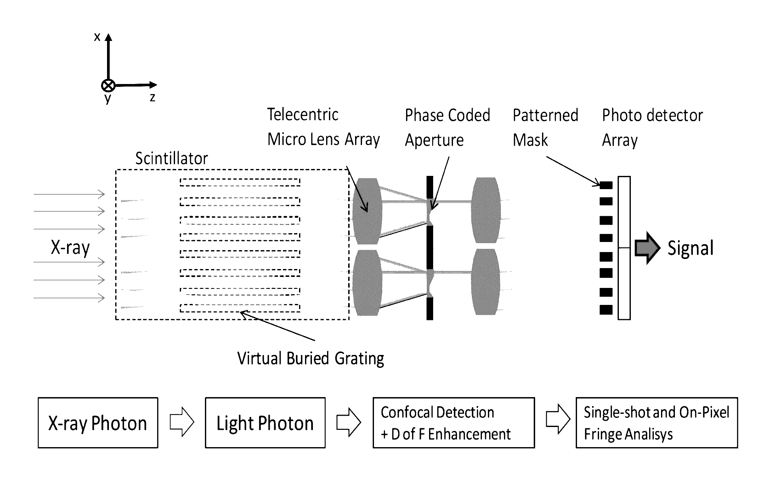
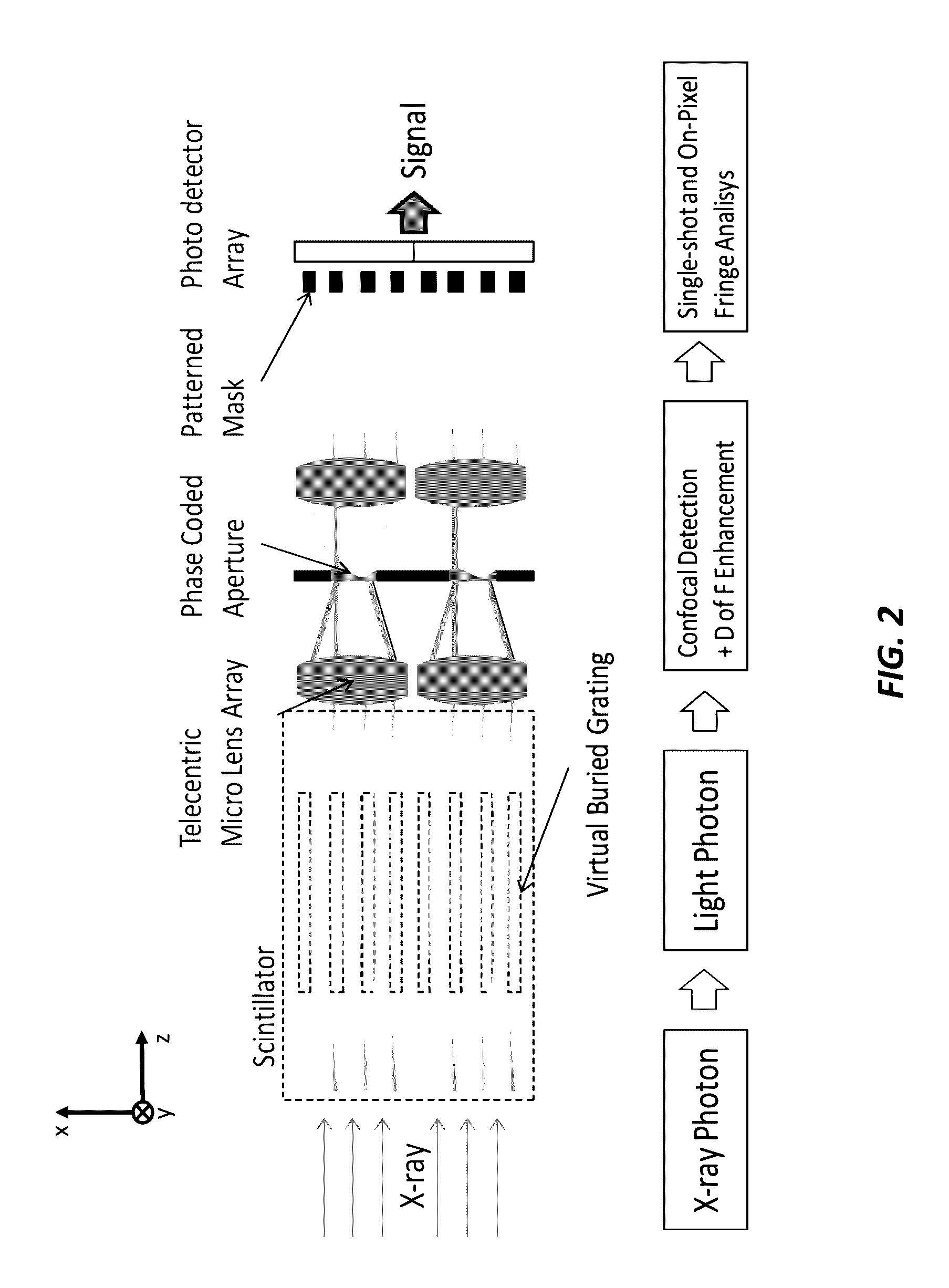
[0025]To overcome such drawbacks of the detector in conventional Talbot X-ray fringe detection system, especially for high X-ray photon energy applications, the current invention provides a Photonic-channeled X-ray Detector Array (PcXDA) that eliminates the analyzer grating from the system, and enables for motionless fringe detection having a large FOV. FIG. 2 shows a schematic diagram of the PcXDA, according to one embodiment of the invention.

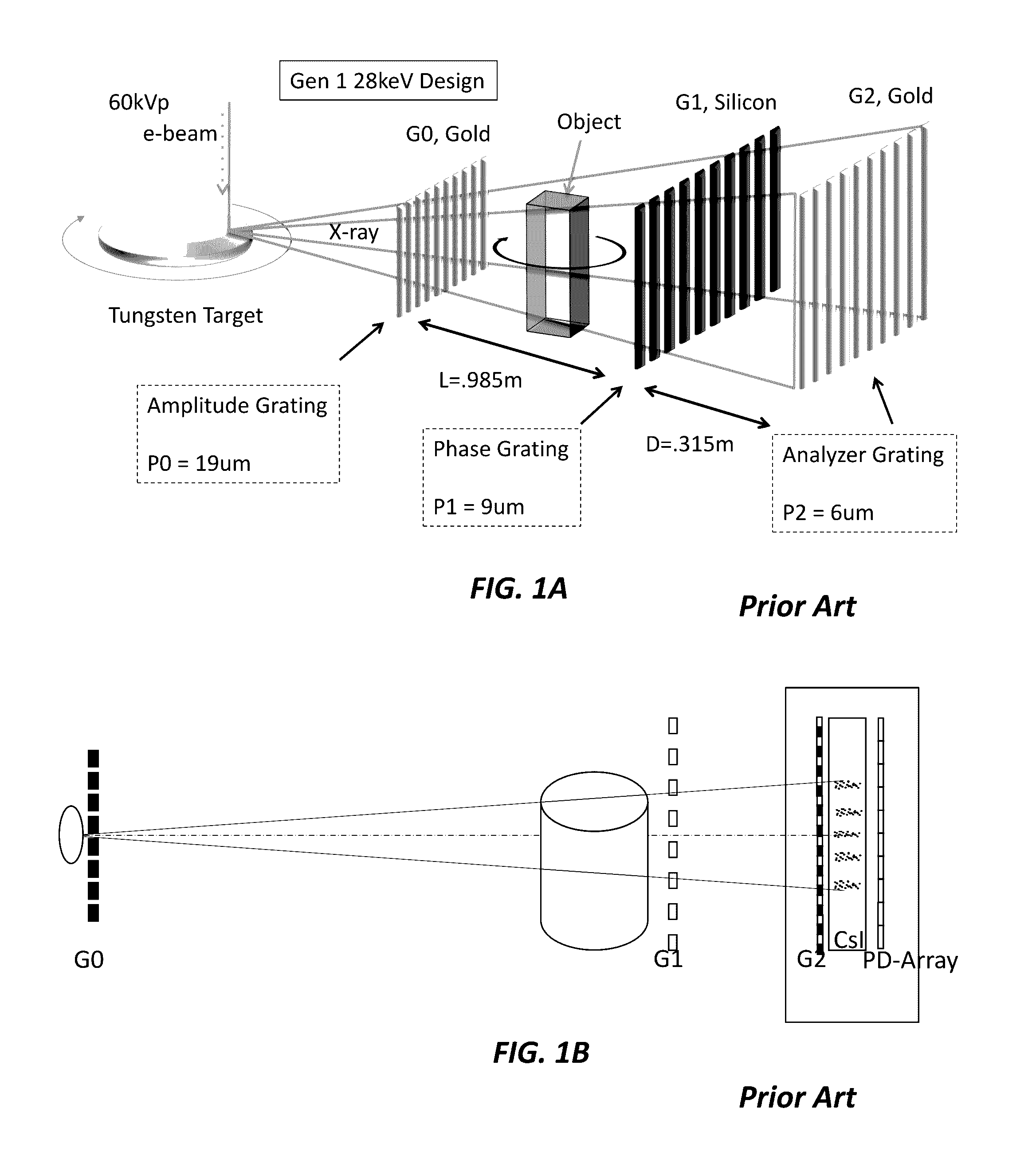
[0026]In a conventional X-ray detector, the X-ray fringe is sampled by the Au / Si G2 grating, where the detection of the fringe distortion is carried out in the X-ray domain. The scintillator converts the sampled X-ray signal to visible photon. The photon is captured by and is transmitted through a fiber optics plate (FOP). Finally photo detector array integrates the photon signal over the region of the photo detector.

[0027]The PcXDA performs conversion of X-rays to visible photons by a scintillator. However, the detection of the fringe distort...


PUM


Abstract

An X-ray detector array includes a scintillator that converts input X-ray radiation to secondary optical radiation output from the scintillator, a first telecentric micro lens array that array receives the secondary optical radiation, a phase coded aperture, where the first telecentric micro lens array directs the secondary optical radiation on the phase coded aperture, a second telecentric micro lens array, where the secondary optical radiation output from the phase coded array is directed to the second telecentric micro lens array, a patterned grating mask, where the second telecentric micro lens array directs the optical beam on the patterned mask, and a photodetector array, where the patterned mask outputs the optical beam in a pattern according to the patterned mask to the photodetector array, where the photodetector array outputs a signal, where a photon fringe pattern is imaged and sampled in the wavelength domain of the radiation from the scintillator.

Description

CROSS-REFERENCE TO RELATED APPLICATIONS[0001]This application claims priority from U.S. Provisional Patent Application 62 / 202,708 filed Aug. 7, 2015, which is incorporated herein by reference.STATEMENT OF GOVERNMENT SPONSORED SUPPORT[0002]This invention was made with Government support under contract HSHQDC-12-C-00002 awarded by the Department of Homeland Security. The Government has certain rights in the invention.FIELD OF THE INVENTION[0003]The invention relates to X-ray detection. More specifically, the invention relates an X-ray detector that eliminates an analyzer grating and enables motionless fringe detection having a large field of view.BACKGROUND OF THE INVENTION[0004]The index of refraction of an object in the visible wavelength domain range can be measured by interferometers, where the index of refraction in the X-ray domain can be measured by X-ray interferometry. In most of the interferometric measurement modalities, the fringe is formed by a coherent light source (for ...

Claims


Application Information

Patent Timeline
IPC IPC(8): G01T1/20G21K1/06G01T1/202
CPCG01T1/2002G21K1/067G01T1/2018G01T1/2023G21K2207/005G01N23/041G01T1/20185
Inventor CHENG, YAO-TEHESSELINK, LAMBERTUSKIM, YOUNG-SIKTAKASHIMA, YUZURUYUEN, MAX
Owner UNIV ARIZONA
Why Eureka
Try Eureka