A method of feeding a sealing medium into a liquor filter and a liquor filter

a technology of sealing medium and liquor filter, which is applied in the direction of filtration separation, lime production, separation processes, etc., can solve the problems of increasing the capacity of the filter, increasing the leakage of sealing water or the need for drainage, and increasing the service life of the outer seal. , to achieve the effect of preventing the leakage of alkaline sealing liquid out of the apparatus, reducing the required feeding pressure, and efficient pumping of sealing medium

Inactive Publication Date: 2017-06-29
ANDRIZ OY
View PDF0 Cites 2 Cited by
  • Summary
  • Abstract
  • Description
  • Claims
  • Application Information

AI Technical Summary

Benefits of technology

[0015]If gas is used as sealing medium, liquor-containing flushing sealing liquid can be added therein. If the lower edge of the liquor filter shaft is below the surface in the basin it is not possible with gas to compensate for the impact of hydrostatic pressure altering in the elevation the way as it is possible when liquid is used. Additionally, gas when leaking into the basin causes intensive bubbling. Then the use of sealing liquid or addition of it into the gas can create a compensating hydrostatic pressure inside the sealing zone in its part that is below the level in the basin. This is essential especially in case of leaking or draining sealing medium, whereby it is not necessary to completely pressurize the sealing medium taking into account the maximum of hydrostatic pressure. The use of liquid sealing medium prevents wearing of sealing surfaces caused by drying and decelerates leaking in tight clearances and therefore it is advantageous to use sealing liquid, if possible even water, admixed to a gaseous sealing medium.
[0016]The innermost seal can be arranged to leak, whereby the sealing medium continuously rinses the surfaces of the sealing zone, cleaning them. Instead of a conventional innermost seal e.g. a shaft of a disc filter can then be surrounded with some other sealing member, such as a narrow gap, a sleeve or a labyrinth seal. Also the outermost seal can be leaking if air is used as the gas. External hydrostatic pressure of a submerged shaft can impact the flows of a sealing zone designed as substantially leaking. The most difficult thing is to arrange an adequate flushing flow at the lowermost edge of the sealing member, where reverse flow into the interior of the sealing zone is most prone to be generated. Reverse flow can be prohibited by arranging on the surfaces of the sealing zone flow barriers, such as notches. The surface of the sealing member and/or the seal housing of the sealing zone and/or the shaft can be threaded, whereby the thread continuously and efficiently pumps the sealing medium. The pumping thread can decrease the required feeding pressure. The clearances of the sealing zone or other channeling of the flushing flows can be eccentric, e.g. so that the clearance is larger on the lower surface of the shaft than in the upper surface. The portion of the innermost sealing member that remains dry can also be designed as leak-proof or with an utmost small clearance, whereby leaking is prevented above the shaft. This is especially advantageous if the sealing medium contains gas.
[0017]Advantageously the alkaline sealing liquid is obtained from the filtrate channels of the filter or group of filters and pressurized with a pump if needed. Preferably, impurities that wear and foul the sealing surfaces have been filtered off the filtrate. The

Problems solved by technology

Dilution caused by sealing water is essentially related to the fact that increasing the capacity of the filter has been limited by limiting the liquid level of the basin below the lower surface of the shaft.
It has not been possible to raise the surface level in the basin over the level of the lower edge of the shaft, because otherwise solids-containing highly abrasive substance, such as lime sludge, would quickly wear the sealing surfaces.
Raising the level to above the lower surface of the shaft, e.g. to mid-way of the shaft, would thus increase the leakage of sealing water or the need for drainage to a huge exte

Method used


Image

  • A method of feeding a sealing medium into a liquor filter and a liquor filter
  • A method of feeding a sealing medium into a liquor filter and a liquor filter
  • A method of feeding a sealing medium into a liquor filter and a liquor filter

Examples


Embodiment Construction

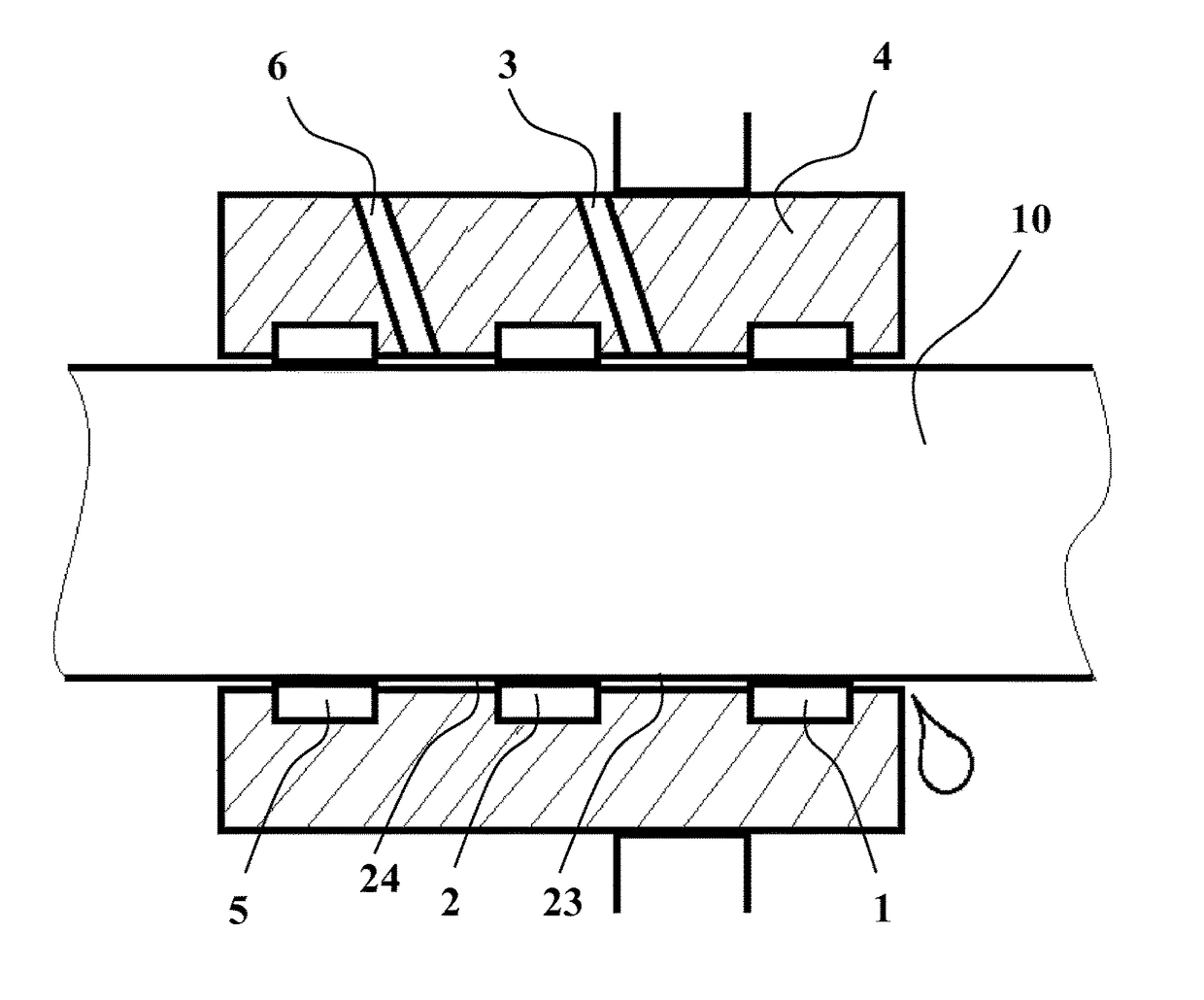
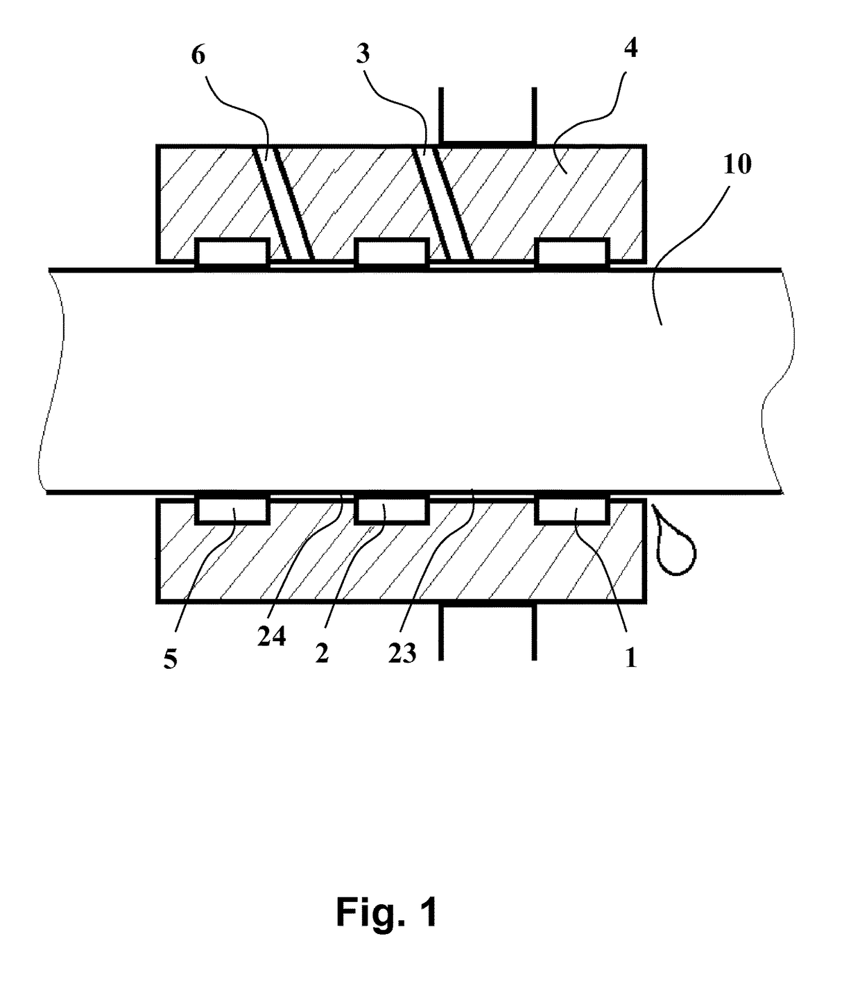
[0024]Axial seals 1, 2 according to FIG. 1, which form an innermost pair of seals, are commonly used in the apparatuses of the chemical pulping industry for sealing the shaft with respect to the frame of the apparatus, such as with respect to the basin of the filter. Typically, sealing water has been led in between the seals 1, 2 via a sealing medium channel 3. The innermost seal 1 seals the shaft 10 on the side of the space to be sealed, i.e. on the side of the filter. The outer seal 2 is located outer than the innermost seal 1, on the side of the outer surface. A pressurized sealing medium channel 3 leads through a seal housing (sealing sleeve) 4 into the innermost sealing zone formed by these seals 1, 2 and the space 23 between them. Leakage from between the innermost seal 1 and the shaft 10 is not very detrimental in view of operation of the seal, but it keeps the innermost sealing surfaces clean despite the corrosive and abrasive impact of the substance inside the filter. Since...


PUM

PropertyMeasurementUnit
Pressureaaaaaaaaaa
Flow rateaaaaaaaaaa
Levelaaaaaaaaaa

Abstract

A method and a liquor filter, in which liquor filter sealing medium is fed via a sealing medium channel (3) into an innermost sealing zone formed by an innermost sealing member (1), an outer seal (2) and the space between them at a causticizing plant of a chemical pulp mill. The sealing medium used is an alkaline sealing liquid and/or gas, which does not substantially dilute the liquor being filtered. Advantageously the sealing medium is filtrate from the liquor filter and/or gas taken from the interior of the liquor filter.

Description

OBJECT OF THE INVENTION[0001]The present invention relates to liquor filters of a the chemical cycle of a chemical pulp mill, in which filters a feed of a sealing medium into an innermost sealing zone formed between an innermost sealing member, an outer sealing member and the space between them is utilized.BACKGROUND OF THE INVENTION[0002]Chemical pulp is produced by cooking wood or annual plants at a high temperature in an alkali-containing solution. In the cooking, cellulose is released and binding agents such as lignin are dissolved in the liquid phase. Chemical pulp is separated from the remaining chemical solution, black liquor, and the black liquor is concentrated by evaporation to a concentration suitable for combustion. In the combustion the organic matter dissolved in the black liquor is burned and the remaining organic chemical smelt can be dissolved into water, weak white liquor or other suitable liquid to form green liquor. This green liquor contains impurities that are ...

Claims


Application Information

Patent Timeline
IPC IPC(8): D21C11/00F16J15/40B01D33/21F16J15/00D21C9/06B01D33/06
CPCD21C11/0078D21C11/0085D21C9/06F16J15/40B01D33/21F16J15/002B01D33/06B01D33/801B01D35/00D21C11/0064Y02P40/40F16J15/18D21C11/00
Inventor HAMMARBERG, TOMMIKOTTILA, MIKAMANTSINEN, MATTISUUTARI, SIMO
Owner ANDRIZ OY
Why Eureka
Try Eureka