
Method of producing press-hardened and coated steel parts at a high productivity rate

a technology of press-hardened and coated steel, which is applied in the direction of radiation-absorbing paints, polyester coatings, metal material coating processes, etc., can solve the problems of not being able to obtain these properties, the method completely disregards certain essential problems, and the heating cycle time is reduced, etc., to achieve the effect of reducing the heating cycle time, high adsorption power, and large specific surface area

Active Publication Date: 2017-09-21
ARCELORMITTAL INVESTIGACION Y DESARROLLO SL
View PDF8 Cites 15 Cited by
  • Summary
  • Abstract
  • Description
  • Claims
  • Application Information

AI Technical Summary

Benefits of technology

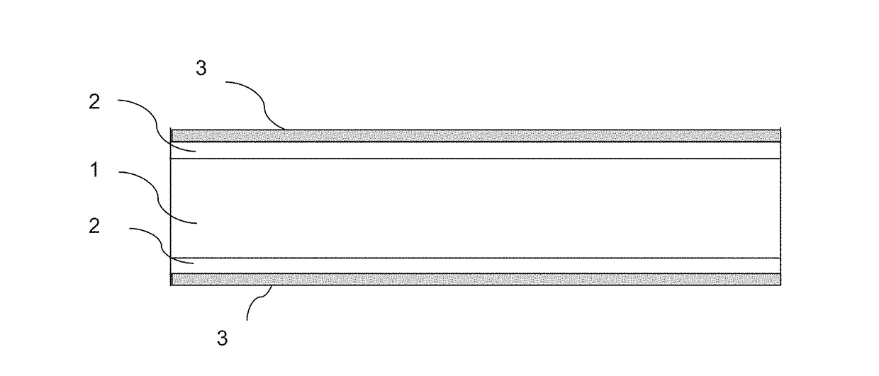
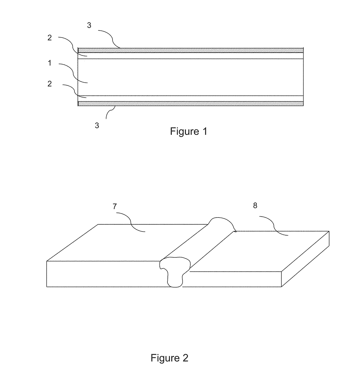
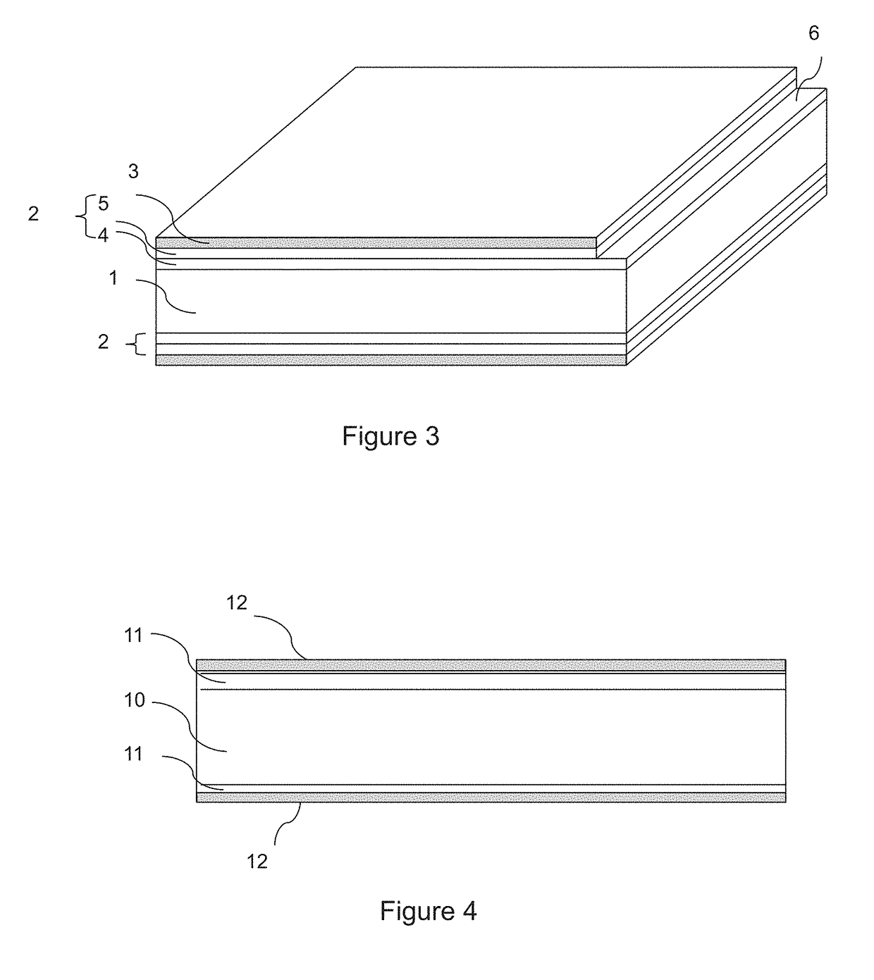
The invention is a method for heating and stamping a blank with a coating of paint that contains carbon particles. The paint is resistant to high temperatures and the carbon particles help to increase the resistance to delayed cracking and corrosion. The method also involves heating the blank to a temperature that allows for the transformation of the paint's binder. The use of polymers that do not contain silicon has been found to be advantageous. The content of carbon pigments in the paint should be limited to 1% to prevent excessive ammonia formation. The carbon pigments can be in the form of graphite or activated carbon. The method can be used with welded blanks, but different heating kinetics can lead to different microstructures and properties in the different parts of the blank.

Problems solved by technology

However, this method requires a prior, time-consuming annealing of the coil.
However, this method completely disregards certain essential problems linked to the later utilization of these parts.
However, as will be shown below, the application of a conventional black paint that is resistant to high temperatures before hot stamping does not make it possible to obtain these properties.
In particular, attempts have been made to devise a method, the results of which are relatively insensitive to the preparation conditions of the pre-coated blank.

Method used


Image

  • Method of producing press-hardened and coated steel parts at a high productivity rate
  • Method of producing press-hardened and coated steel parts at a high productivity rate
  • Method of producing press-hardened and coated steel parts at a high productivity rate

Examples


example 1

[0097]Blanks 1 mm thick were provided made of steel having the following composition in percent by weight: 0.228% C, 1.189% Mn, 0.014% P, 0.001% S, 0.275% Si, 0.028% Al, 0.034% Ti, 0.003% B, 0.177% Cr, the balance being iron and impurities resulting from processing. These blanks comprise a pre-coating 24 μm thick on each surface, containing 9% by weight silicon, 3% by weight iron, the balance being aluminum and unavoidable impurities. On some of these blanks, a layer was then deposited by roll coating over the entirety of the two surfaces composed of polymer and carbon pigments, in aqueous phase, under the different conditions indicated in the table below. The acrylic phenoxy resin contains less than 0.2% nitrogen on the deposited layer. The percent by weight of carbon pigments in these roll-coated layers is indicated in Table 1 below. The layers deposited were dried by passing through a kiln at 70° C. for 5 minutes.

TABLE 1Test conditionsPercent byPercent byweight ofweight ofgraphit...

example 2

[0116]The resistance to different forms of corrosion of hot stamped and press hardened parts fabricated was evaluated according to the conditions I2 (AlSi pre-coating and painting according to the invention) and R2 (AlSi pre-coating alone) from Table 1.

[0117]The resistance to cosmetic corrosion was determined under the following conditions: scratches of different depths were made, affecting only the coating (condition A) or also affecting the substrate (condition B) of hot stamped parts. These parts were subjected to cycles of temperature and moisture in a saline mist for six weeks under the conditions described in the “New VDA Test 233-102”, which is in itself known. The width of blistering at the level of the scratch was then measured. The results are presented in Table 5.

TABLE 5Results of cosmetic corrosionWidth of blistering (mm)Width of blistering (mm)Condition ACondition BI22.74R22.64.2

[0118]Compared to the reference test R2, it was found that the application of paint accordin...

example 3

[0122]Blanks made of 22MnB5 steel 1, 5 and 2 mm thick comprising on both their sides a pre-coating 23 μm thick containing 9% Si and 3% Fe, the balance being aluminum and unavoidable impurities, were acquired. On some of the blanks, a layer composed of polymer and carbon pigments was deposited by roll coating over the entirety of the two principal surfaces under conditions I2 according to the invention indicated in Table 1. The other blanks were not painted (condition R).

[0123]The blanks were heated to 900° C., held at this temperature for one minute, then hot stamped and hardened by holding them in the stamping tool. The diffusible hydrogen content was measured using a thermal desorption analysis method, which is in itself known. The diffusible hydrogen content of these blanks is presented in Table 7.

TABLE 7Diffusible hydrogen contentThickness ofDiffusible hydrogenCoatingthe flan (mm)content (ppm)I21.50.15R1.50.21I220.17R20.25

[0124]The deposit of the specific paint according to the ...


PUM

PropertyMeasurementUnit
thicknessaaaaaaaaaa
temperatureaaaaaaaaaa
thicknessaaaaaaaaaa

Abstract

A sheet or blank is provided which includes a substrate and pre-coating on at least one face of the substrate. A polymerized layer overlies at least a part of the pre-coating and has a thickness from 2 μm to 30 μm, a nitrogen content of less than 1% by weight, carbon pigments in a quantity from 3 to 30% by weight and does not include a polymer with silicon. A welded blank, part and fabrication methods are also provided.

Description

[0001]This is a Continuation of U.S. patent application Ser. No. 15 / 301,316, filed Sep. 30, 2016 as a National Phase Application of International Patent Application PCT / IB2015 / 000143, filed Feb. 13, 2015 which claims priority to International Patent Application PCT / IB2014 / 000455, filed Mar. 31, 2014, the disclosures of which are hereby incorporated by reference herein.[0002]This invention relates to a fabrication method for parts from pre-coated steel sheets that are heated, stamped and then hardened during a cooling obtained by holding in a pressing tool; these parts are intended to be used as, among other things, structural elements in automotive vehicles to perform anti-intrusion or energy absorption functions. Parts of this type can also be used, for example, for the fabrication of tools or parts of agricultural machinery.BACKGROUND[0003]In this type of applications, the objective is to produce steel parts that combine high mechanical strength, good corrosion resistance and good...

Claims


Application Information

Patent Timeline
Patent Type & Authority Applications(United States)
IPC IPC(8): C21D9/50C21D1/673C09D5/00C09D5/32C23C2/12C23C2/26C23C2/28C09D167/02C09D163/00C09D133/02C09D123/12C09D123/06C08K3/04B21D35/00B21D22/02C22C38/32C22C38/28C22C38/06C22C38/04C22C38/00C22C38/02C23F17/00C21D9/46C21D6/00C21D1/22C21D8/02C23C2/40
CPCC21D8/0278C21D1/673C09D5/00C09D5/32C23C2/12C23C2/26C23C2/28C09D167/02C09D163/00C09D133/02C09D123/12C09D123/06C08K2201/001C08K3/04B21D35/007B21D22/022C22C38/32C22C38/28C22C38/06C22C38/04C22C38/002C22C38/02C23F17/00C21D2211/008C21D2211/002C21D2211/001C21D9/50C21D9/46C21D8/0247C21D8/0205C21D6/008C21D6/005C21D6/002C21D1/22C23C2/40C23C2/29C09D133/00
Inventor SANADRES, MICHELDESSAIN, CHRISTINE
Owner ARCELORMITTAL INVESTIGACION Y DESARROLLO SL
Learn More