Capacitor and method of production thereof

a technology of capacitors and capacitors, applied in the direction of wound capacitors, fixed capacitor details, fixed capacitors, etc., can solve the problems of local breakdown, electric field strength, and breakage voltag

Active Publication Date: 2017-10-19
CAPACITOR SCI
View PDF0 Cites 17 Cited by
  • Summary
  • Abstract
  • Description
  • Claims
  • Application Information

AI Technical Summary

Benefits of technology

[0014]Embodiments of the present invention provides a capacitor comprising a first electrode, a second electrode, and a dielectric layer of molecular material disposed between said first and second electrodes. Said electrodes are flat and planar and positioned parallel to each other. The molecular material is described by the general formula:Dp-(Core)-Hq,   (I)where Core is a polarizable conductive anisometric core, having conjugated π-systems, and characterized by a longitudinal axis, D and H are insulating substituents, and p and q are numbers of the D and H substituents accordingly. The insulating substituents are selectively attached to any available positions on the polarizable anisometric core including on apex positions and lateral positions as related the longitudinal axis of the Core, and p and q are independently selected from values 1, 2, 3, 4, and 5. And Core possesses one or more dopant groups that enhance polarizability.
[0015]A method of producing a capacitor, which comprises the steps of a) preparation of a conducting substrate serving as one of the electrodes, b) application of a molecular material on the substrate, c) formation of the solid layer molecular material layer on the substrate, and d) formation of the second electrode on the solid molecular material layer, wherein the molecular material is described by the general formula:Dp-(Core)-Hq   (I)where Core is a conductive and polarizable anisometric core, having conjugated π-systems, and characterized by a longitudinal axis, D and H are insulating substituents, and p and q are numbers of the D and H substituents accordingly. The insulating substituents are selectively attached to any available positions on the polarizable anisometric core including apex positions and lateral positions as related the longitudinal axis of the Core, and p and q are independently selected from values 1, 2, 3, 4, and 5. And Core possesses one or more dopant groups that enhance polarizability.

Problems solved by technology

Electrodes and leads introduce an equivalent series resistance, and dielectric layer has limitation to an electric field strength which results in a breakdown voltage.
In particular, sharp edges or points hugely increase the electric field strength locally and can lead to a local breakdown.
Once a local breakdown starts at any point, the breakdown will quickly “trace” through the dielectric layer till it reaches the opposite electrode and causes a short circuit.
Presence of impurities in the dielectric or imperfections of the crystal structure can result in an avalanche breakdown as observed in semiconductor devices, such as avalanche diodes and avalanche transistors.
A major drawback of this material is a possible occurrence of percolation and formation of at least one continuous conductive path under electric field with probability of such an event increasing with an increase of the electric field.
A drawback of this device is that blocking layers of high dielectric permittivity located directly in contact with electrodes can lead to destruction of the energy storage device.
Another drawback of current devices is that they require the expensive manufacturing procedure of vacuum deposition of all layers.
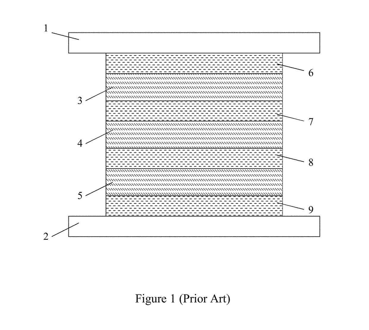
Compared to batteries, capacitors can store energy with very high power density, i.e. charge / recharge rates, have long shelf life with little degradation, and can be charged and discharged (cycled) hundreds of thousands or millions of times. However, capacitors often do not store energy in a small volume or weight as in a case of batteries, or at low energy storage cost, which makes capacitors impractical for some applications, for example electric vehicles.

Method used


Image

  • Capacitor and method of production thereof
  • Capacitor and method of production thereof
  • Capacitor and method of production thereof

Examples


example 1

[0060]Example 1 describes a capacitor comprising a dielectric layer formed with the solid molecular material of lamellar structure as shown in FIG. 5.

[0061]The capacitor comprises two electrodes 13 and 14, the dielectric layer 15 which comprises the conductive anisometric stacks 12 formed with the polarizable anisometric cores, and isotropic insulating sublayers 16. Polyaniline (PANI) is used as the polarizable anisometric core, and fluorinated alkyl substituents are used as the insulating substituents. The conductive anisometric stacks formed with polyaniline (PANI) have the dielectric permittivity εcor equal to 10,000. Thickness of each insulating sublayers formed by the substituents is approximately dins=2 nm, and number of the insulating sublayers nins is equal to 500. Electrodes 13 and 14 are made of copper. Dielectric permittivity of the insulating sublayers is equal to 2.2 (i.e. εins=2.2) and its breakdown voltage is equal to 1 V / nm. The working voltage of the capacitor does ...


PUM

PropertyMeasurementUnit
thicknessaaaaaaaaaa
thicknessaaaaaaaaaa
dielectricaaaaaaaaaa

Abstract

A capacitor includes a first electrode, a second electrode, and a dielectric layer of molecular material disposed between said first and second electrodes. The molecular material is described by the general formula:Dp-(Core)- Hq,where Core is a polarizable conductive anisometric core, having conjugated π-systems, and characterized by a longitudinal axis, D and H are insulating substituents, and p and q are numbers of the D and H substituents accordingly. And Core possesses at least one dopant group that enhances polarizability.

Description

CLAIM OF PRIORITY[0001]The present application is a continuation-in-part of U.S. patent application Ser. No. 14 / 710,491, filed May 12, 2016, the entire contents of which are incorporated herein by reference. U.S. patent application Ser. No. 14 / 710,491 claims the priority benefit of U.S. Provisional Patent Application No. 61 / 991,871 filed May 12, 2015, the entire contents of which are incorporated herein by reference.FIELD OF THE INVENTION[0002]The present invention relates generally to passive components of electrical circuit and more particularly to a capacitor intended for energy storage and method of production thereof.BACKGROUND OF THE INVENTION[0003]A capacitor is a passive electronic component that is used to store energy in the form of an electrostatic field, and comprises a pair of electrodes separated by a dielectric layer. When a potential difference exists between two electrodes, an electric field is present in the dielectric layer. This field stores energy, and an ideal ...

Claims


Application Information

Patent Timeline
Patent Type & Authority Applications(United States)
IPC IPC(8): H01G4/18H02J7/00H01G4/38C08G73/02H01G4/01H01G4/008H01G4/002H01G4/32H02J7/34
CPCH01G4/186H01G4/01H01G4/008H01G4/002H02J7/345H01G4/32H02J7/0068C08G73/0266H01G4/18H01G4/38H01G4/14H01G4/40H01L29/00
Inventor LAZAREV, PAVEL IVANSHARP, BARRY K.FURUTA, PAULLI, YANKELLY-MORGAN, IAN SGROBINSON, MATTHEW R.MEMBRENO, DANIEL
Owner CAPACITOR SCI
Why Eureka
Try Eureka