Additive manufacturing and integrated impact post-treatment

Inactive Publication Date: 2017-11-16
BAE SYSTEMS PLC
View PDF7 Cites 25 Cited by
  • Summary
  • Abstract
  • Description
  • Claims
  • Application Information

AI Technical Summary

Benefits of technology

[0010]The invention provides a method of mitigating distortion for each layer during the building of additive layer manufactured parts. No

Problems solved by technology

It is a problem with this type of manufacturing that, during weld pool creation, the work piece is subject to intense localised heating.
This heating creates steep thermal gradients in the work piece between the molten material in the weld pool and the cold material which surrounds it.
It is these residual compressive stresses which cause b

Method used


Image

  • Additive manufacturing and integrated impact post-treatment
  • Additive manufacturing and integrated impact post-treatment
  • Additive manufacturing and integrated impact post-treatment

Examples


Embodiment Construction

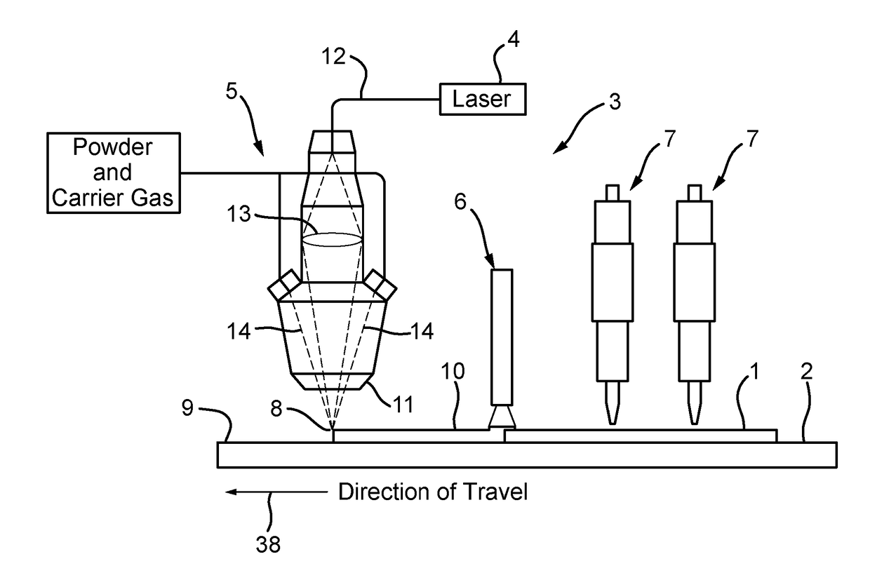
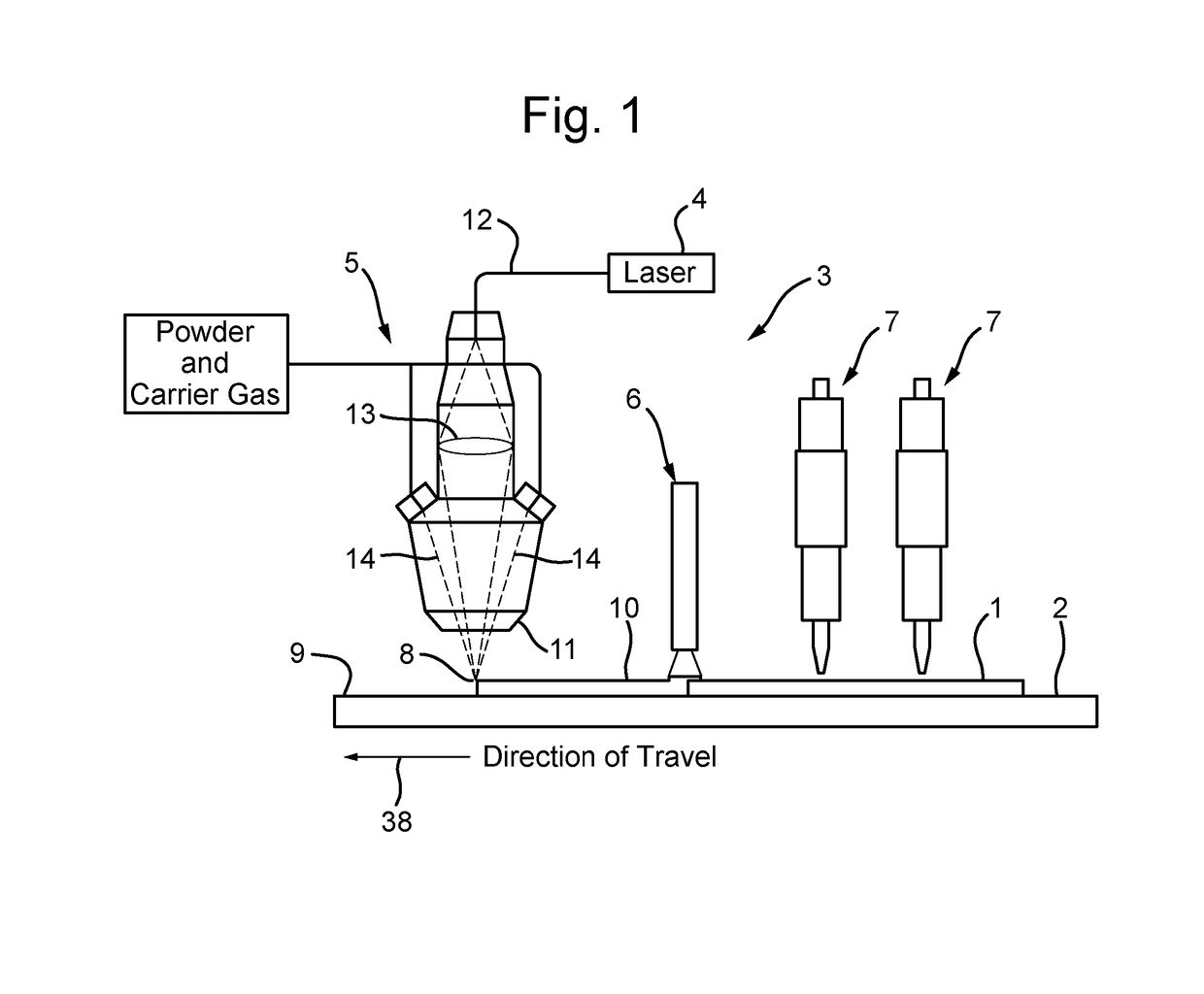
[0032]The terminology “Additive Manufacturing” is used herein to refer to all additive processes that may be used to produce functional, complex objects, layer by layer, without moulds or dies e.g. by providing material (e.g. metal or plastic) typically in the form of a powder or a wire, and, using a powerful heat source such as a laser beam, electron beam or an electric, or plasma welding arc, melting an amount of that material and depositing the melted material (e.g. on a base plate / work piece), and subsequently building layers of material upon each preceding layer.

[0033]Additive Manufacture (AM) may also be known inter alia as 3D printing, Direct Digital Manufacturing (DDM), Digital Manufacturing (DM), Additive Layer Manufacturing (ALM), Rapid Manufacturing (RM), Laser Engineering Net Shaping (LENS), Direct Metal Deposition, Direct Manufacturing, Electron Beam Melting, Laser Melting, Freeform Fabrication, Laser Cladding, Direct Metal Laser Sintering.

[0034]Referring to FIG. 1, app...


PUM

PropertyMeasurementUnit
Thicknessaaaaaaaaaa
Thicknessaaaaaaaaaa
Frequencyaaaaaaaaaa

Abstract

A method and apparatus for forming an object by additive layer manufacturing. The method comprises: a) applying, by a heat source (4), heat to a portion of a surface of a workpiece (1) sufficient to melt said portion; b) adding material to the melted portion and moving the heat source (4) relative to the workpiece (1) whereby progressively to form a layer of material (10) on the workpiece (1); c) cooling the formed layer (10) to bring at least part of the layer (10) to a state of crystallisation, there producing a modified workpiece; d) peening, using a plurality of independently controllable impact treatment devices (7), the modified work-piece so as to plastically deform the cooled at least part of the layer (10); and repeating steps a) to d) as required whereby to form the object.

Description

FIELD OF THE INVENTION[0001]This invention relates to additive manufacturing (AM) and in particular to apparatus and a method to relieve stress in a component manufactured by an AM process.BACKGROUND[0002]Additive manufacturing (AM) is a manufacturing process that is able to produce a functional complex part, layer by layer, without moulds or dies. This process uses a powerful heat source such as a laser beam or a welding arc to melt a controlled amount of metal in the form of metallic powder or wire, which is then deposited, initially, on a base plate. Subsequent layers are then built up upon each preceding layer. As opposed to conventional machining processes, this computer-aided manufacturing (CAM) technology builds complete functional parts or, alternatively, builds features on existing components, by adding material rather than by removing it.[0003]Currently known AM manufacturing techniques include: Laser Blown Powder, Laser Powder Bed, and Wire and Arc technologies. Laser Blo...

Claims


Application Information

Patent Timeline
IPC IPC(8): B23K26/00B23K9/04B33Y30/00B23K26/34B33Y10/00B23K26/70B23K26/144B33Y40/00B23P9/04B23K9/32B23K103/04B23K103/14
CPCB23K26/0093B33Y10/00B33Y30/00B33Y40/00B23P9/04B23K9/04B23K9/32B23K26/34B23K26/703B23K26/144B23K2203/04B23K2203/14B22F3/24B24C1/10C21D7/06B22F2999/00C22F1/183B23P15/00B23K10/027B23K15/002B23K15/0026B23K15/0086B23K15/0093B23K26/0006B23K26/1476B23K26/342B23K2103/05B24B39/06B23K2103/14Y02P10/25B22F10/25B22F10/85B33Y40/20B22F2203/13B23K9/042B23P25/00B22F10/00B23K2103/04B24B39/00
Inventor SIDHU, JAGJITWESCOTT, ANDREW DAVID
Owner BAE SYSTEMS PLC
Why Eureka
Try Eureka