

Organic electroluminescent element
- Summary
- Abstract
- Description
- Claims
- Application Information
AI Technical Summary
Benefits of technology
Problems solved by technology
Method used
Image

Examples
preparation examples 1 to 12
01 to LE-12
[0092]Compounds represented by the following LE-01 to LE-12 were prepared as bipolar compounds useful in the present invention and were measured for ΔEst, triplet energy, ionization potential, EHOMO−ELUMO, electron motility, and hole motility, using methods known in the art, and the results are summarized in Table 1, below.
TABLE 1Calculated(B3LYP / 6 −31G*)ΔEstMeasured(S1 −TripletIonizationEHOMO −ElectronHoleCpd.T1)energypotentialELUMOmotilitymotilityLE-0.422.785.923.496.8 × 10−47.3 × 10−501LE-0.522.685.883.457.3 × 10−45.9 × 10−502LE-0.472.715.933.568.1 × 10−47.6 × 10−503LE-0.572.736.123.446.6 × 10−45.8 × 10−504LE-0.512.815.973.637.3 × 10−48.3 × 10−505LE-0.482.836.163.646.8 × 10−47.6 × 10−506LE-0.492.825.973.607.8 × 10−48.1 × 10−507LE-0.552.805.963.587.9 × 10−37.8 × 10−508LE-0.522.826.013.627.3 × 10−47.7 × 10−509LE-0.472.725.893.458.5 × 10−47.4 × 10−510LE-0.382.655.873.416.7 × 10−46.8 × 10−511LE-0.412.716.013.517.7 × 10−47.6 × 10−512*For hole motility and electron motility,...
examples 1 to 12
lue Fluorescent Organic Light-Emitting Element
[0093]A glass substrate coated with an ITO (indium tin oxide) thin film 1500 Å thick was cleansed by ultrasonication in distilled water and then in a solvent such as isopropyl alcohol, acetone, methanol, etc. and then dried. The glass substrate was transferred to a UV OZONE cleaner (Power sonic 405, Hwashin Tech) and cleaned for 5 min using UV, and transferred to a vacuum evaporator.
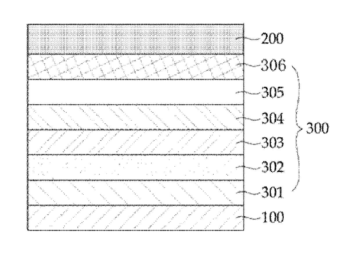
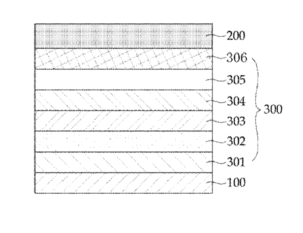
[0094]On the transparent ITO electrode (substrate) thus obtained, a hole injection layer, a hole transport layer, a light-emitting layer, a lifetime enhancement layer, an electron transport layer, an electron injection layer, and a cathode were deposited in that order to fabricate organic electroluminescent elements. Structures of the fabricated elements are as shown in Table 2, below.
TABLE 2HoleHoleLight-LifetimeElectroninjectiontransportemittingEnhancementtransportlayerlayerlayerLayerlayerCathodeCpd.DS-205NPBAND +5% DS-LE-01 toAlq3Al(Doosan405LE-12Corporati...
experimental example 1
[0098]The elements fabricated in Examples 1 to 12 and Comparative Examples 1 and 2 were measured for driving voltage at a current density of 10 mA / cm2, current efficiency, emitting peak, and lifetime (T97), and the results are summarized in Table 3, below.
TABLE 3DrivingCurrentEmittingVolt.EfficiencyPeakLifespanCpd.(V)(cd / A)(nm)(hr, T97)ExampleLE-4.37.145863101ExampleLE-4.26.945859202ExampleLE-4.67.045762303ExampleLE-4.17.345858404ExampleLE-4.08.045841505ExampleLE-4.27.945838606ExampleLE-3.88.245842707ExampleLE-3.98.345735808ExampleLE-4.17.845839909ExampleLE-4.27.9458641010ExampleLE-4.57.0458751111ExampleLE-4.37.4457691212C.—4.75.645832Example1C.BCP5.35.945828Example2*For lifespan, a measurement was made of time taken for luminance to decrease to 97% of the initial value thereof, using a lifetime test system (McScience).
[0099]As is understood from the data of Table 3, the organic electroluminescent elements of Examples 1 to 12, each comprising a lifetime enhancement layer in accordan...
PUM
| Property | Measurement | Unit |
|---|---|---|
| Energy | aaaaa | aaaaa |
| Energy | aaaaa | aaaaa |
| Energy | aaaaa | aaaaa |
Abstract
Description
Claims
Application Information