

Rectifying element, method for producing same, and wireless communication device
a technology of rectifying elements and rectifying elements, which is applied in the structure of radiating elements, solid-state devices, instruments, etc., can solve the problems of insufficient dispersion of cnts, unstable performance of rectifying elements, and increased rectifying elements, and achieve excellent rectifying properties and simple process
- Summary
- Abstract
- Description
- Claims
- Application Information
AI Technical Summary
Benefits of technology
Problems solved by technology
Method used
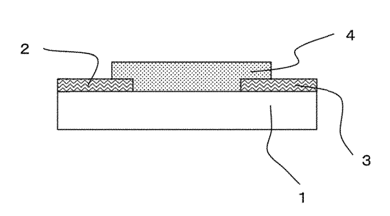
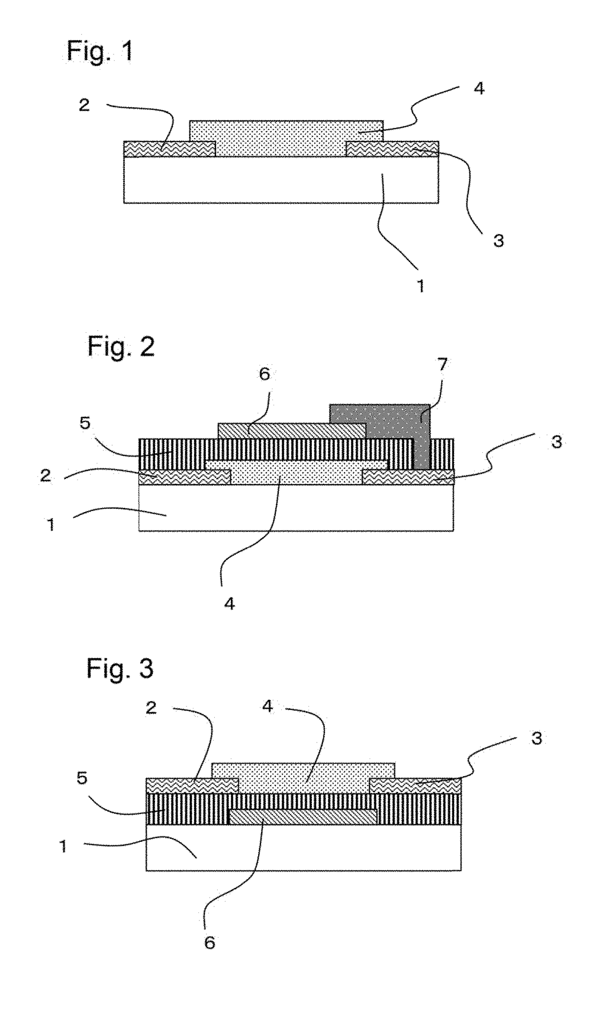
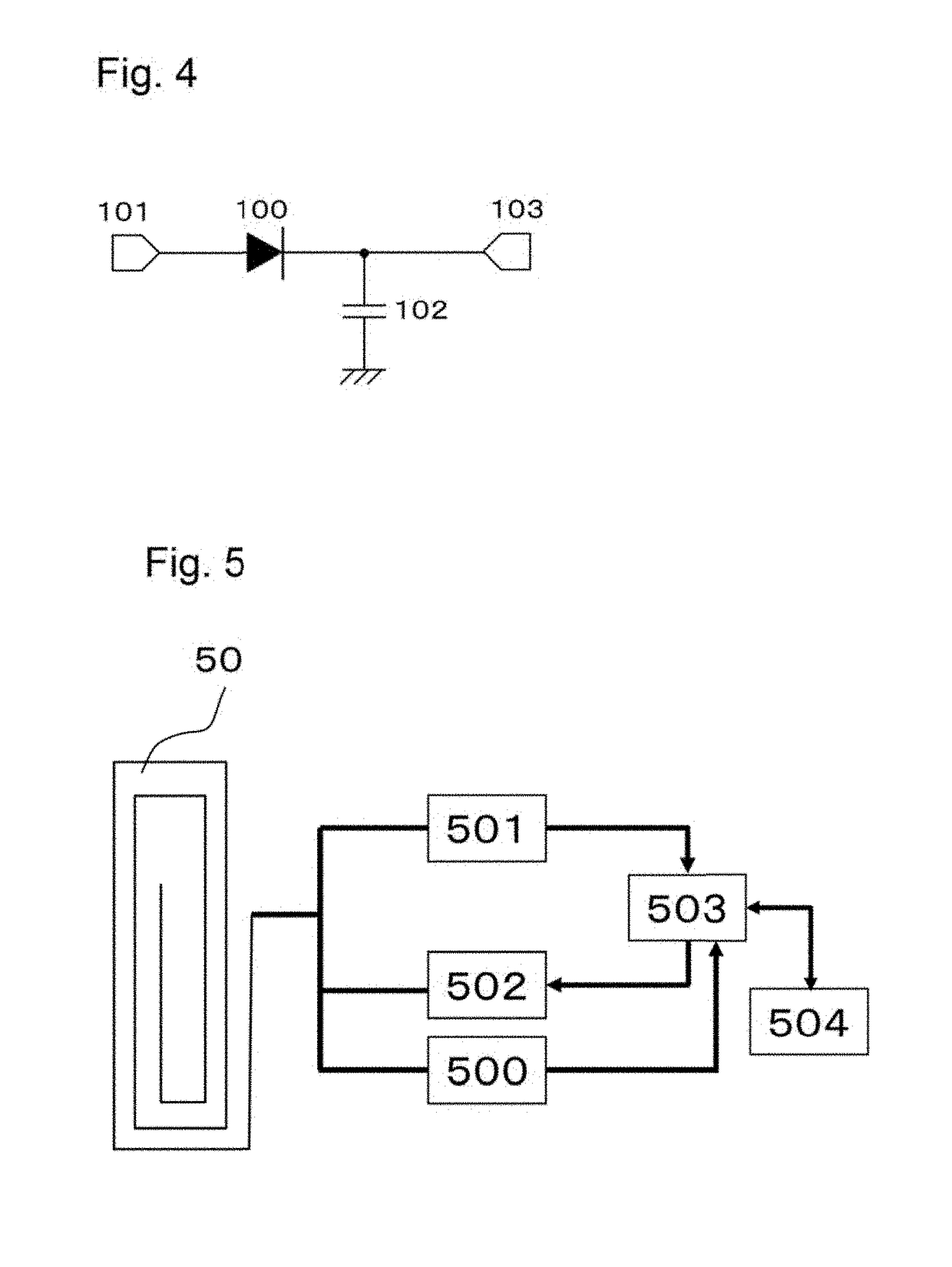
Image

Examples
synthetic example 1
Compound P1 (Binder)
[0173]Copolymerization ratio (by mass): ethyl acrylate (also referred to as “EA”, hereinafter) / 2-ethylhexyl methacrylate (also referred to as “2-EHMA”, hereinafter) / styrene (also referred to as “St”, hereinafter) / glycidyl methacrylate (also referred to as “GMA”, hereinafter) / acrylic acid (also referred to as “AA”, hereinafter)=20 / 40 / 20 / 5 / 15.
[0174]Diethylene glycol monoethyl ether acetate (also referred to as “DMEA”, hereinafter) (150 g) was charged in a reaction vessel in a nitrogen atmosphere, and the reaction vessel was heated to 80° C. using an oil bath. To the oil bath was dropwisely added a mixture of EA (20 g), 2-EHMA (40 g), St (20 g), AA (15 g), 2,2′-azobisisobutyronitrile (0.8 g) and DMEA (10 g) over 1 hour. After the completion of the dropwise addition, the polymerization reaction was carried out for additional 6 hours. Subsequently, hydroquinone monomethyl ether (1 g) was added to the resultant solution to terminate the polymerization reaction. Subsequ...
synthetic example 2
Compound P2 (Binder)
[0175]Copolymerization ratio (by mass): a bifunctional epoxy acrylate monomer (epoxy ester 3002A; manufactured by Kyoeisha Chemical Co., Ltd.) / a bifunctional epoxy acrylate monomer (epoxy ester 70PA; manufactured by Kyoeisha Chemical Co., Ltd.) / GMA / St / AA=20 / 40 / 5 / 20 / 15.
[0176]Diethylene glycol monoethyl ether acetate (also referred to as “DMEA”, hereinafter) (150 g) was charged in a reaction vessel in a nitrogen atmosphere, and the reaction vessel was heated to 80° C. using an oil bath. To the oil bath was dropwisely added a mixture of an epoxy ester 3002A (20 g), an epoxy ester 70PA (40 g), St (20 g), AA (15 g), 2,2′-azobisisobutyronitrile (0.8 g) and DMEA (10 g) over 1 hour. After the completion of the dropwise addition, the polymerization reaction was carried out for additional 6 hours. Subsequently, hydroquinone monomethyl ether (1 g) was added to the resultant solution to terminate the polymerization reaction. Subsequently, a mixture of GMA (5 g), triethylbenz...
synthetic example 3
Compound P3 (Binder) Urethane-Modified Compound of Compound P2
[0177]Diethylene glycol monoethyl ether acetate (also referred to as “DMEA”, hereinafter) (100 g) was charged in a reaction vessel in a nitrogen atmosphere, and the reaction vessel was heated to 80° C. using an oil bath. To the oil bath was dropwisely added a mixture of the photosensitive component P2 (10 g), n-hexyl isocyanate (3.5 g) and DMEA (10 g) over 1 hour. After the completion of the dropwise addition, the reaction was carried out for additional 3 hours. The resultant reaction solution was purified with methanol to remove unreacted impurities, and then the resultant product was dried under vacuum for 24 hours to produce a compound P3 which had a urethane bond.
PUM
| Property | Measurement | Unit |
|---|---|---|
| distance | aaaaa | aaaaa |
| total length | aaaaa | aaaaa |
| length | aaaaa | aaaaa |
Abstract
Description
Claims
Application Information