
Silicon anode active material and preparation method therefor

a technology of active materials and silicon anodes, applied in the field of secondary battery technology, to achieve the effects of high capacity, improved life span, and high efficiency

Active Publication Date: 2018-02-01
NEXEON LTD
View PDF4 Cites 20 Cited by
  • Summary
  • Abstract
  • Description
  • Claims
  • Application Information

AI Technical Summary

Benefits of technology

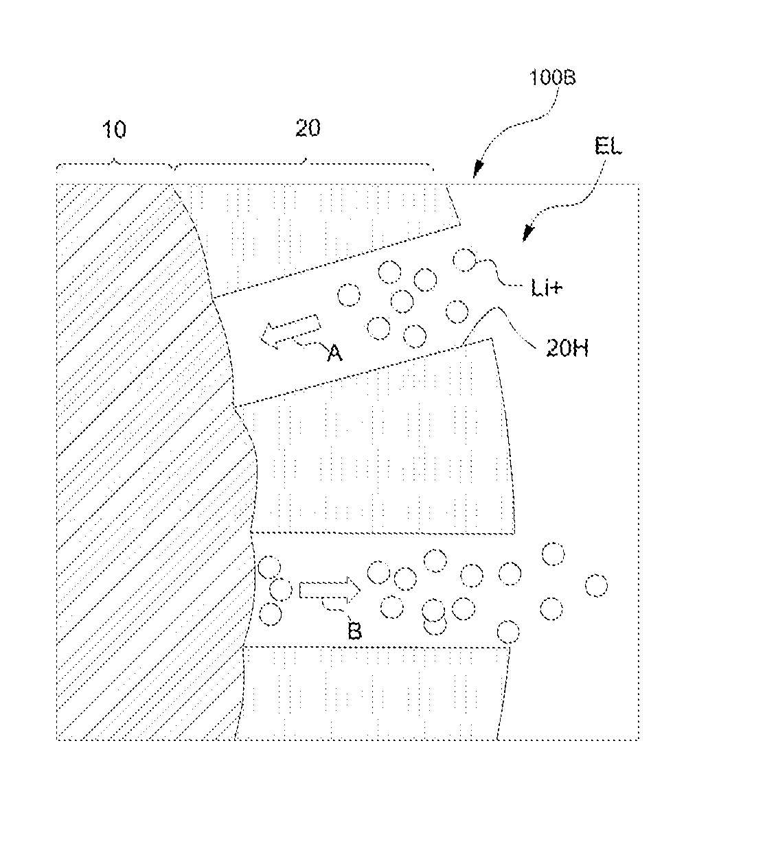
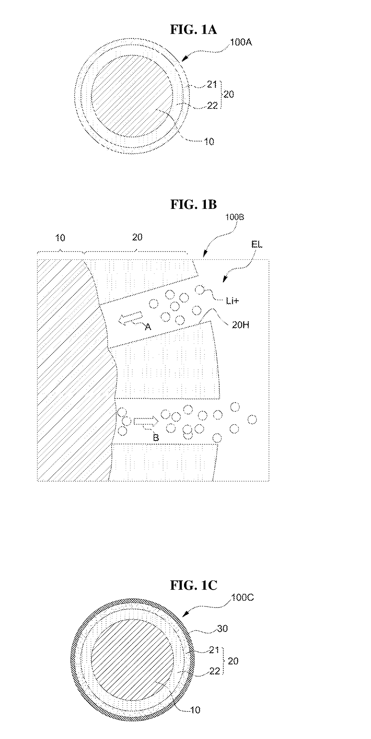
This patent describes a new material for making batteries with a silicon anode. The material has a core of pure silicon particles and two layers: a silicon oxide layer and a silicon carbide layer. This double clamping layer helps to stabilize the material and prevent it from swelling or shrinking during charging and discharging of the battery. The silicon oxide layer acts as a source for forming the silicon carbide layer, which enables the material to have high capacity and a longer lifespan for the battery. By using a liquid carbon precursor to produce the silicon carbide layer, the material can be produced economically and quickly. Overall, this material is promising for making batteries with high efficiency and output.

Problems solved by technology

However, since the volume of the silicon anode material expands by about 4 times during charging of the silicon anode material, due to the volume change during charging and discharging, the electrical connection between the active materials may be broken, the active material may be separated from a current collector, and the active material may be eroded by electrolyte, which are a barrier to its practical use.

Method used


Image

  • Silicon anode active material and preparation method therefor
  • Silicon anode active material and preparation method therefor
  • Silicon anode active material and preparation method therefor

Examples


experimental example 1

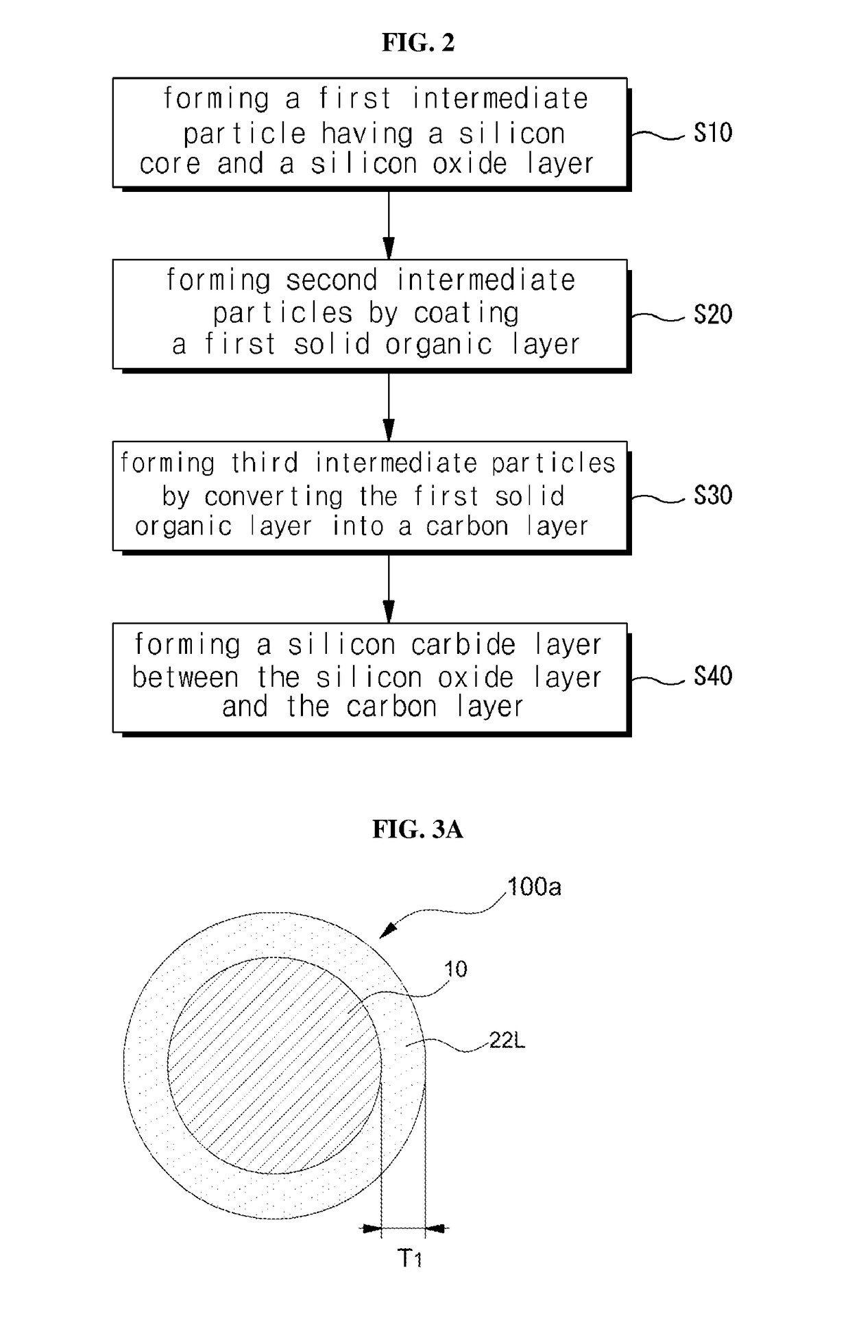
[0068]The carbon precursor PVP was dissolved in distilled water at room temperature, and the intermediate particles having the silicon oxide layer formed on the surface of the silicon core were dispersed in the PVP aqueous solution. The radius of the silicon core was 20 nm on average and the thickness of the silicon oxide layer was 2 nm. In order to form a sufficient amount of the solid organic layer, the concentration of PAN was increased to 10 wt %.

[0069]The dispersed aqueous solution was stirred for about 30 minutes to obtain silicon particles, and a solvent on the particles was evaporated to prepare the intermediate particles coated with a solid organic layer as a carbon precursor layer on the surface. Thereafter, the intermediate particles were heat-treated at 800° C. for 1 hour in an Ar gas atmosphere to prepare intermediate particles having a carbon layer formed thereon. Then, the intermediate particles having the carbon layer formed thereon were heat-treated at 1,200° C. for...

experimental example 2

[0070]As in Experimental Example 1, PVP as a carbon precursor was dissolved in distilled water at room temperature, and silicon particles having a silicon oxide layer formed on the surface of the silicon core were dispersed in the PVP aqueous solution. The silicon particles are the same as the silicon particles of Experimental Example 1, the average radius of the silicon core is 20 nm, and the thickness of the silicon oxide layer is about 2 nm.

[0071]After the dispersion aqueous solution was stirred for about 30 minutes, silicon particles were obtained and the solvent on the particle was evaporated to prepare the intermediate particles having a carbon precursor layer coated on the surface thereof as a solid organic layer. Thereafter, the intermediate particles were heat-treated at 1,200° C. for 2 hours in an Ar gas atmosphere to form a silicon carbide layer and a carbon layer sequentially on the silicon oxide layer of the intermediate particles.

[0072]FIG. 6 is a high-resolution trans...


PUM

PropertyMeasurementUnit
thicknessaaaaaaaaaa
temperatureaaaaaaaaaa

Abstract

The present invention relates to a silicon anode active material capable of high capacity and high output, and a method for fabricating the same. A silicon anode active material according to an embodiment of the present invention includes a silicon core including silicon particles; and a double clamping layer having a silicon carbide layer on the silicon core and a silicon oxide layer between the silicon core and the silicon carbide layer.

Description

TECHNICAL FIELD[0001]The present invention relates to secondary battery technology, and more particularly, to a silicon anode active material and a method of fabricating the same.BACKGROUND ART[0002]Recently, demand for secondary batteries such as lithium batteries, lithium ion batteries, and lithium ion polymer batteries is greatly increasing. The secondary battery is a rechargeable battery using an electrode material having excellent reversibility and the secondary battery may be a nickel-hydrogen (Ni-MH) battery, a lithium battery or a lithium ion battery depending on the anode and the cathode active material. Such secondary batteries are increasingly widely being applied to various applications as power supply sources for information technology (IT) devices such as smart phones, portable computers, and electronic paper, or for transportation systems such as electric vehicles.[0003]A carbon-based material having a theoretical capacity of 372 mAh / g is generally applied as a materi...

Claims


Application Information

Patent Timeline
Patent Type & Authority Applications(United States)
IPC IPC(8): H01M4/587H01M4/88C01B32/956H01M4/38
CPCH01M4/587H01M4/386H01M4/8885C01B32/956H01M2004/027H01M4/622H01M4/62Y02E60/50Y02E60/10H01M4/366H01M4/134H01M4/625H01M4/1395H01M4/0471H01M10/0525C01B32/984H01M4/38
Inventor CHO, YOUNG TAICHOI, YONG GILPARK, SEONLEE, YOUNG JAESEO, HEE YOUNGPARK, JEE HYELEE, YONG EUIHONG, YOUNG JIN
Owner NEXEON LTD
Learn More