
Retinal tissue regeneration

a retinal tissue and tissue technology, applied in the field of tissue engineering, can solve the problems of polymeric scaffolds, expected improvement in retinal regeneration, irreversible blindness,

Active Publication Date: 2018-02-22
SEPAHVANDI AZADEH
View PDF1 Cites 4 Cited by
  • Summary
  • Abstract
  • Description
  • Claims
  • Application Information

AI Technical Summary

Benefits of technology

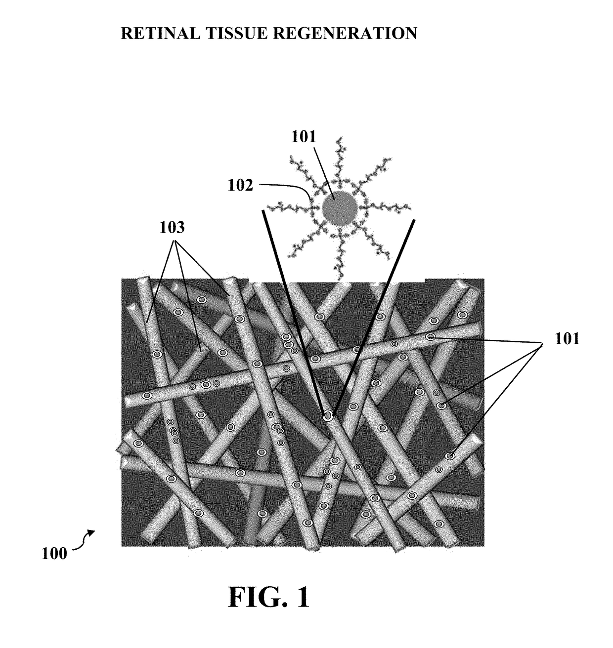
The present disclosure describes a method for regenerating retinal tissue using a luminescent scaffold. The scaffold is made by dispersing luminescent particles in a polymeric matrix and can be implanted in the retina to stimulate retinal cells and promote regeneration. The scaffold can be made by synthesizing luminescent particles and dispersing them in a polymeric matrix using a homogenizer or an electrospinning process. The method can also involve using a green light from the luminescent scaffold to absorb the light and stimulate the retinal cells. The patent text provides a technical solution for regenerating retinal tissue and has potential applications in the field of regenerative medicine and tissue engineering.

Problems solved by technology

Degenerative retinal diseases such as retinitis pigmentosa and age-related macular affects millions of people, and without any treatment, these diseases lead to an irreversible blindness.
Recent advances in fabrication of polymers such as polyglycolic acid (PGA), polylactic acid (PLLA), poly-DL-lactic acid (PDLLA), hyaluronic acid (HA), polycaprolactone (PCL), and chitosan (CS) led to development of polymeric scaffolds which are implanted in retina area; however, absence of proper signaling in these polymeric scaffolds wouldn't result in an expected improvement in regeneration of retina.
It is hard to recognize PEG layers in this TEM image, because the PEG molecules have a poor contrast due to their low electron density, and the PEG coating may be damaged during the preparation technique.
However, as the concentration of the particles in electrospun solution increases, the bead formation is delayed.
Moreover, increasing percentage of the luminescent particles causes the porosity of the luminescent scaffold become low.
As a result, the scaffold with 30% luminescent particles seems to be more biocompatible for both including shorter wavelength and middle intense emission.
Moreover, the luminescent scaffold with 10% of luminescent particles is quiet pliable and this luminescent scaffold has inadequate strength.

Method used


Image

  • Retinal tissue regeneration
  • Retinal tissue regeneration
  • Retinal tissue regeneration

Examples


example 1

of Luminescent Nanoparticles

[0079]The luminescent particles may be applied for retinal tissue engineering, for example, retina regeneration; therefore, luminescent particles may be exposed to different cells in retina, and size of the luminescent particles should be same as the cellular size in nanometer scale. Therefore, the sol-gel method was used in this example to synthesize SrAl2O4:Eu2+Dy3+ particles to obtain the particles with a desired size. In this example, SrAl2O4:Eu2+Dy3+ luminescent nanoparticles were synthesized.

[0080]In order to prepare SrAl2O4:Eu2+Dy3+ luminescent nanoparticles with high bright emission and long afterglow, Eu2+Dy3+ co-doped strontium aluminate (SrAl2O4) luminescent nanoparticles were prepared as follows. At first, analytical graded reagents such as aluminum nitrate (Al(NO3)3), strontium nitrate (Sr(NO3)2), dysprosium nitrate (Dy(NO3)3) and europium nitrate (Eu(NO3)3) were dissolved in distilled water with the following molar ratios: (Sr(NO3)2 0.97, Eu...

example 2

on of the Luminescent Scaffold

[0090]In this example, a scaffold with SrAl2O4:Eu2+Dy3+ luminescent nanoparticles was prepared utilizing the following steps. At first, a copolymer of chitosan and polycaprolactone (CS-PCL) was prepared by grafting ε-caprolactone oligomers (PCL) onto hydroxyl groups of chitosan (CS). Therefore, about 2.0 grams of CS, which has about 12 mmol of glucosamine units, and about 20 mL of MeSO3H was inserted to a flame-dried 50 mL flask to form a solution. In order to dissolve chitosan (CS) completely, the solution was stirred for approximately 30 minutes at 45° C.

[0091]After that, about 16.58 grams of ε-caprolactone monomer was injected to the solution to form a copolymer mixture. The copolymer mixture was stirred for about 5 hours under nitrogen atmosphere at a temperature of about 45° C.; then the copolymer mixture was filtered to collect the resulting CS-PCL copolymer. After that, in order to adjust the filtrate pH, the filtrate was added into a solution co...

example 3

nescence Properties of the Luminescent Scaffolds

[0110]In this example, photoluminescence properties of the luminescent nanoparticles and the prepared scaffolds are studied. Determination of photoluminescence properties of PEGylated SrAl2O4:Eu2+Dy3+ luminescent nanoparticles was done using Perking Elmer LS-55 fluorescence spectrophotometer with a 230 V pulsed Xenon source for excitation.

[0111]The samples were irradiated by UV light at a wavelength of 390 nm for 10 minutes prior to the emission measurements. After that, SrAl2O4:Eu2+Dy3+ luminescent nanoparticles were excited by a light beam with a prominent peak at a wavelength of 390 nm.

[0112]The emission spectra show a broad band peak at a wavelength of 512 nm which represents a transition from 4f6 5d1 electron configuration to 4f7 electron configuration of excited Eu2+ ions. While the typical emission peak of the luminescent particles is 520 nm, this shift towards shorter wavelengths, 512 nm, can be explained considering the sol-ge...


PUM

PropertyMeasurementUnit
Concentrationaaaaaaaaaa

Abstract

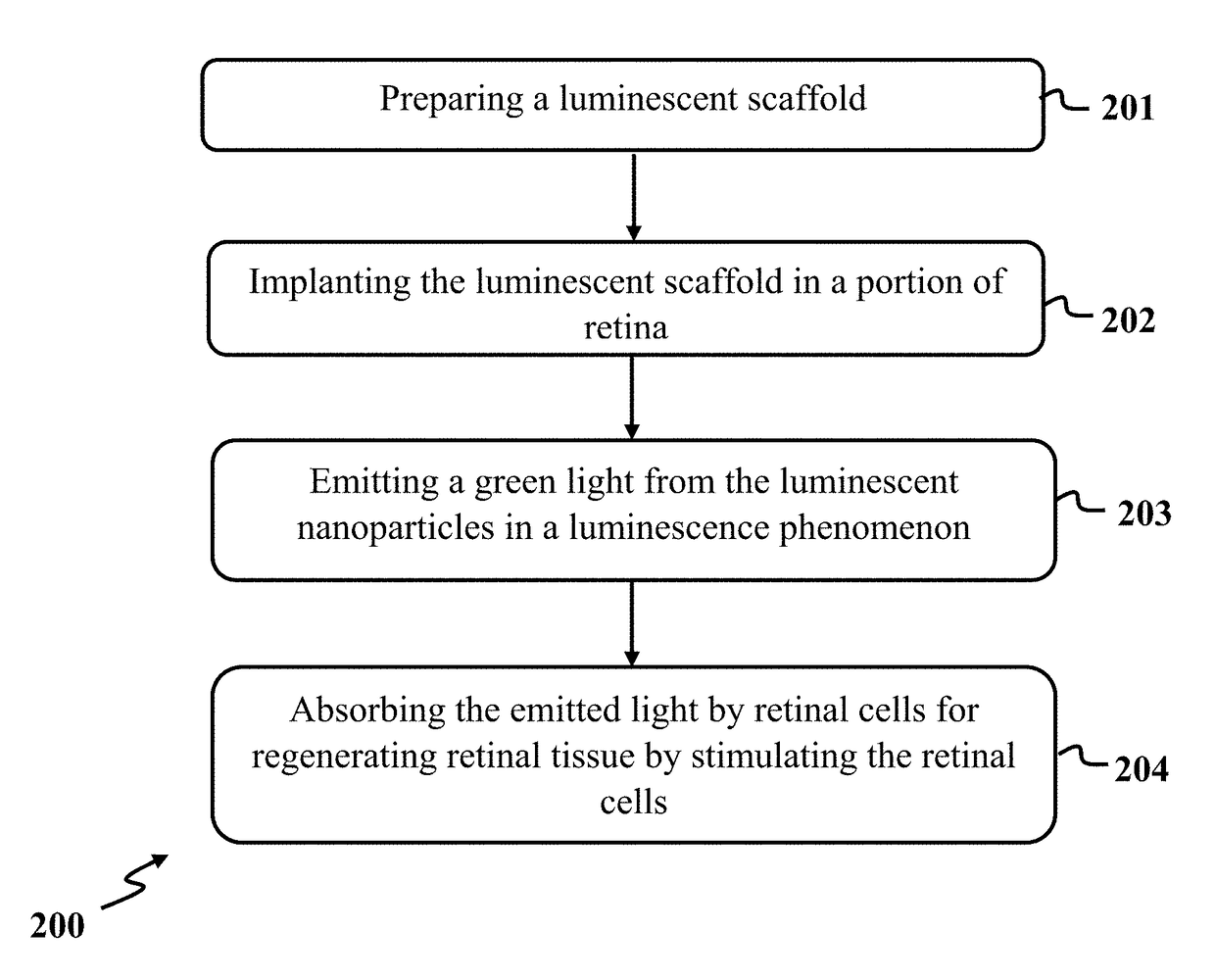
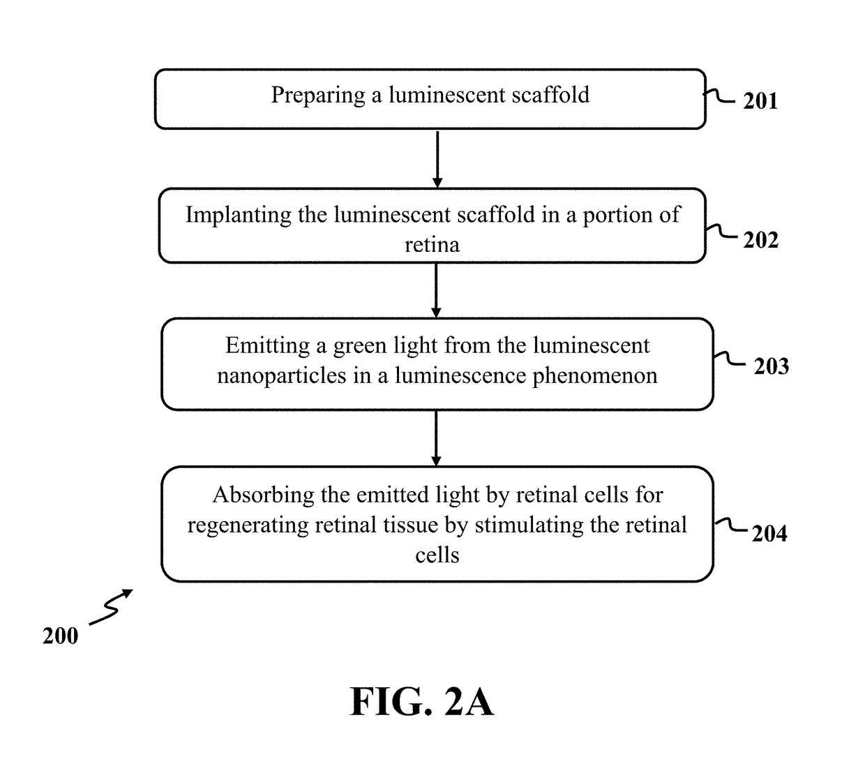
Disclosed herein is a method for regenerating retinal tissue which includes preparing a luminescent scaffold, implanting the luminescent scaffold in a portion of retina, for example subretinal area, emitting a green light from the luminescent nanoparticles in a luminescence phenomenon, and absorbing the emitted light by retinal cells for regenerating retinal tissue by stimulating the retinal cells. Moreover, preparing a luminescent scaffold may comprise synthesizing a plurality of luminescent particles, dispersing the luminescent particles in a polymeric matrix to form a luminescent composite, and electrospinning the luminescent composite to form the luminescent scaffold.

Description

CROSS-REFERENCE TO RELATED APPLICATION[0001]This application claims the benefit of priority from pending U.S. Provisional Patent Application Ser. No. 62 / 405,923, filed on Oct. 9, 2016, and entitled “RETINAL TISSUE REGENERATION BY BIOCOMPATIBLE SRAL2O4:EU2+DY3 LUMINESCENCE NANOPARTICLES,” which is incorporated herein by reference in its entirety.TECHNICAL FIELD[0002]The present disclosure generally relates to tissue engineering, particularly to retinal tissue regeneration, and more particularly to retinal tissue regeneration by luminescence particles.BACKGROUND[0003]Retina is one of the well-developed structures of eyes with several layers of neurons, which are interconnected by synapses. Degenerative retinal diseases such as retinitis pigmentosa and age-related macular affects millions of people, and without any treatment, these diseases lead to an irreversible blindness. In order to treat degenerative retinal diseases, extensive research has been conducted and various treatment app...

Claims


Application Information

Patent Timeline
IPC IPC(8): A61N5/06A61L27/26A61L27/10A61K41/00B05D1/00
CPCA61N5/062A61L27/26A61L27/10A61K41/0023B05D1/007A61N2005/0663A61L2430/16A61K41/0038D01D5/003D01F1/04D01F6/84D01F9/00C09K11/02C09K11/7773C09K11/7792A61L27/446A61L2300/624A61L2400/12A61N5/0601A61N2005/0648A61N2005/0662A61K41/17A61F2009/00863A61F9/00727C12N2533/40
Inventor SEPAHVANDI, AZADEH
Owner SEPAHVANDI AZADEH
Learn More