A Process for Producing Hydrogen and Graphitic Carbon from Hydrocarbons

a graphitic carbon and hydrocarbon technology, applied in chemical/physical/physical-chemical process catalysts, metal/metal-oxide/metal-hydroxide catalysts, physical/chemical process catalysts, etc., can solve the problems of carbon dioxide, not being exploited commercially, harmful to the environment, etc., to achieve higher purity, higher value, and high purity

Active Publication Date: 2018-03-08
HAZER GRP
View PDF2 Cites 5 Cited by
  • Summary
  • Abstract
  • Description
  • Claims
  • Application Information

AI Technical Summary

Benefits of technology

[0056]In a second form of the present invention where multiple reactors are used in a series which allows catalyst flow between reactors, unreacted hydrocarbon gas is provided to each reactor. In this arrangement, hydrocarbon gas is continuously flowed through the reactor. Unreacted catalyst is provided in the lowest pressure reactor, which following the catalytic conversion of the methane, produces a partially deactivated catalyst. The partially deactivated catalyst is transferred into the next reactor of higher pressure in the series for further catalytic conversion of methane. The higher pressure of the reactor allows for further deactivation of the catalyst. The transfer of the partially deactivated catalyst repeats along multiple reactors of increasing pressure. When unreacted hydrocarbon gas is provided in each reactor, the applicant has termed this arrangement a parallel catalyst multiple pressure reactor (parallel catalyst MPR).
[0057]In a third form of the present invention the multiple reactors are arranged in a series which allows for both the hydrocarbon gas and catalyst to flow between reactors in opposite directions. In this arrangement, unreacted catalyst is provided in the lowest pressure reactor and unreacted hydrocarbon gas is provided in the highest pressure reactor. The catalyst is transferred between the chambers of increasing pressure counter-currently to the gas flow between the chambers. The applicant has termed this arrangement a counter-current multiple pressure reactor (counter-current MPR). The partially deactivated catalyst retains activity in the higher pressure reactors, and the resultant graphite product has higher purity (as % of mass) with correspondingly higher value.
[0058]The inventors have found that the counter-current MPR arrangement allows for more complete conversion of the hydrocarbon gas and a higher purity graphitic carbon product. As there is no catalyst flow in parallel gas MPRs or no gas flow in parallel catalyst MPRs, the design is much simpler than the counter-current MPR.

Problems solved by technology

Conventional methods of producing hydrogen from fossil fuels however produce carbon dioxide (natural gas steam reforming and coal gasification) which is harmful to the environment.
Whilst the above process is known, it has not been exploited commercially for a number of economic reasons.
This primarily relates to the underlying catalyst costs, both in the initial supply, as well as costs in recycling and regenerating the catalyst.
The vast majority of researchers in this area have utilised expensive and complex supported catalysts which, despite their high catalyst activity and product yield, result in extremely high catalyst turnover costs.
These costs are a significant barrier to commercialising the use of such catalysts.

Method used


Image

  • A Process for Producing Hydrogen and Graphitic Carbon from Hydrocarbons
  • A Process for Producing Hydrogen and Graphitic Carbon from Hydrocarbons
  • A Process for Producing Hydrogen and Graphitic Carbon from Hydrocarbons

Examples


example 1

[0158]The use of iron ore as the catalyst for the economical production of hydrogen and graphite via the thereto-catalytic decomposition of methane.

Experimental Details

[0159]The present invention provides a method which enables the use of low grade iron oxide as a catalyst for the decomposition of methane. In order to demonstrate the catalytic activity of the low grade iron oxide catalyst of the present invention, samples of low grade iron oxide were compared to high grade iron oxide samples. Two types of high grade iron oxide were tested; hematite (99%, <5 μm, Sigma-Aldrich) and magnetite (95%, <5 μm, Sigma-Aldrich); as well as two iron ore samples: Hematite ore (Pilbara mine) and goethite ore (Yandi mine). The ore samples were milled to <150 μm but otherwise untreated. The ‘as received’ compositional data, particle size distribution, and surface area of all the samples are detailed in Table 1.

TABLE 1Compositional, particle size and surface area data for the iron oxide samples.CaMn...

example 2

[0165]Thermo-catalytic methane decomposition using counter-current MPR.

Counter-Current.

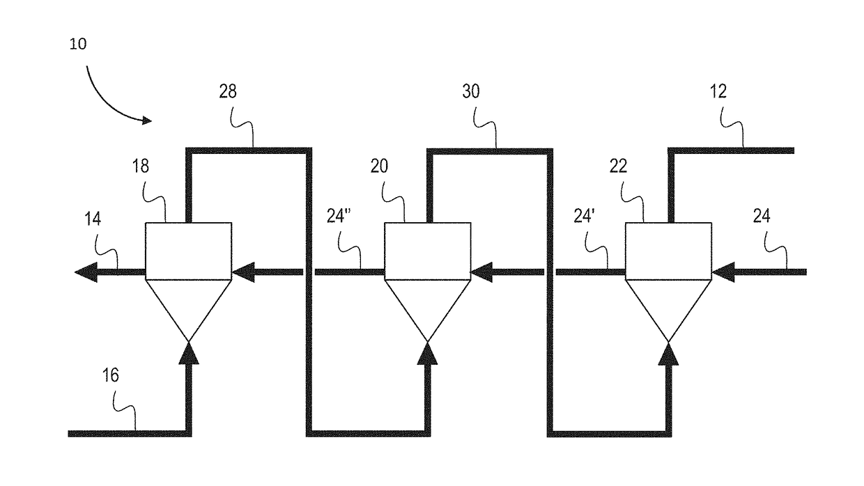
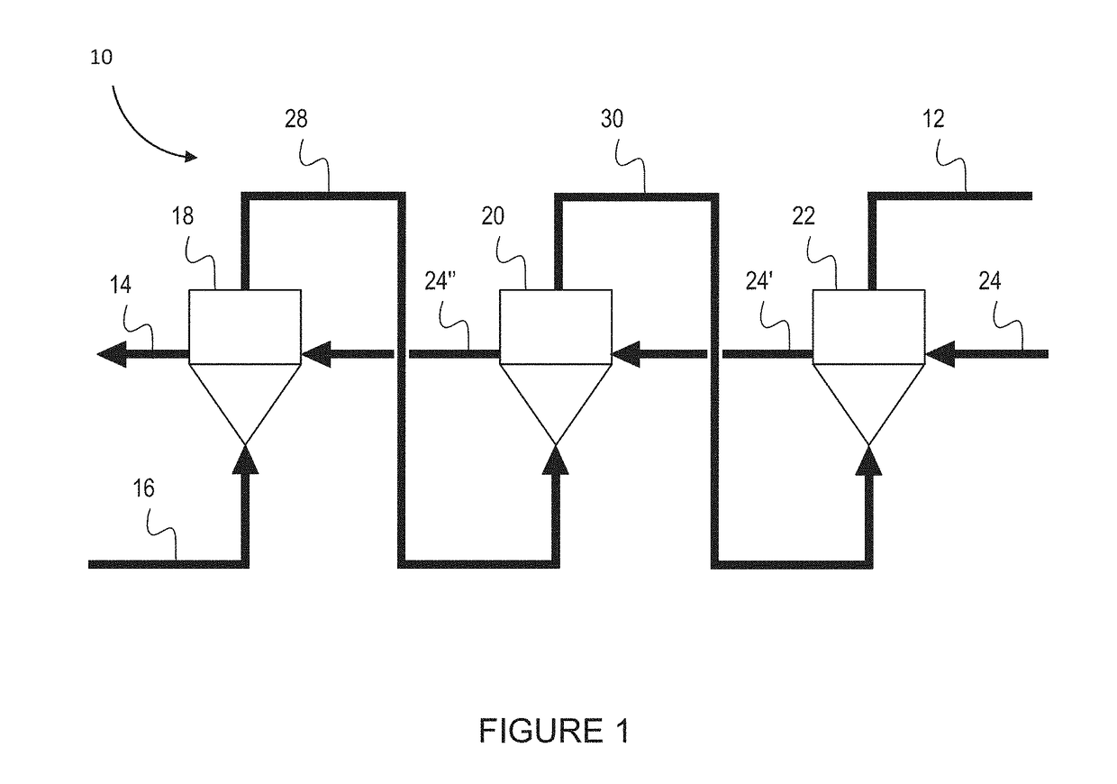
[0166]A three reactor counter-current MPR was set up in a cascade arrangement as shown in the schematic of FIG. 7.

[0167]Experimental evaluation of the counter-current MPR system was undertaken using a static (non-continuous) system. This was done by testing the effect of pressure on the methane conversion efficiency and the carbon yield. The results confirmed that an increase in pressure lowered the methane conversion, and increased the carbon yield, and conversely a lower pressure increase of the methane conversion and lowered the total carbon yield.

Experimental Details

[0168]Effect of reaction pressure on the methane conversion limit.

[0169]The reactor set-up comprised three independent reactor stages (3×½″ OD 316SS Swagelok, 700 mm length) with different set back-pressures (12 bar, 4 bar and atmospheric) and an isothermal temperature of 850° C. Instead of linking the reactors in series, each was ...

example 3

Beneficiation of Iron Ore.

Experimental Details

[0193]Typical low grade iron ore rock consists of distinct sections of high grade iron oxide and low grade counterpart. This type of rock is known as banded iron formation (BIF). A 6.39 g sample of BIF iron ore was prepared, an analysis of the characteristics are shown in Table 3.

TABLE 3Sample AnalysisOXIDESiO2TiO2Al2O3Fe2O3Mn3O4MgOCaONa2OK2OP2O5SO3Iron ore10.620.060.1188.80.010.120.020.230.010.03richsectionIron ore84.10.040.1412.90.070.210.110.030.02poorsectionOXIDECr2O3ZrO2SrOZnOCuONiOBaOPbOL.O.i.TOTALIron ore0.130.020.010.010.271.98102.43richsectionIron ore0.210.43199.26poorsection

[0194]The sample was loaded into a static reactor bed and was contacted at 900° C. with methane gas and atmospheric pressure for a period of 4 hours. Following reaction, the high grade iron oxide band had fragmented whereas the low grade counterpart was largely unaffected.

[0195]Without wishing to be bound by theory it is understood by the inventors that the ...


PUM

PropertyMeasurementUnit
temperatureaaaaaaaaaa
pressureaaaaaaaaaa

Abstract

In accordance with the present invention, there is provided a process for producing hydrogen and graphitic carbon from a hydrocarbon gas comprising: contacting at a temperature between 600° C. and 1000° C. the catalyst with the hydrocarbon gas to catalytically convert at least a portion of the hydrocarbon gas to hydrogen and graphitic carbon, wherein the catalyst is a low grade iron oxide.

Description

FIELD OF THE INVENTION[0001]The present invention relates to a process for producing hydrogen and graphitic carbon.BACKGROUND ART[0002]Hydrogen has many commercial uses, such as a clean and environmentally friendly alternative to fuel in internal combustion engines. Carbon, or more particularly graphite, is considered a key material in the emerging green technology market. It has been shown to be useful in energy storage, electrical conduction devices, catalyst supports, lubrication additives and modern electronics equipment. All references to carbon within this patent relates to the graphitic form of carbon, therefore these terms are used interchangeably throughout.[0003]Conventional methods of producing hydrogen from fossil fuels however produce carbon dioxide (natural gas steam reforming and coal gasification) which is harmful to the environment.[0004]Natural gas can be catalytically cracked into both hydrogen gas and solid carbon according to Equation (1).CH4→C+2H2   (1)[0005]In...

Claims


Application Information

Patent Timeline
Patent Type & Authority Applications(United States)
IPC IPC(8): C01B3/26C01B3/30C01B32/205B01J8/00B01J8/26B01J19/24B01J19/00B01J23/745
CPCB01J23/745C01B2203/1241C01B2203/1047C01B2203/0277B01J2203/061C01B3/26C01B3/30C01B32/205B01J8/0005B01J8/26B01J19/245B01J19/0013B01J19/2445B01J2219/00162C01B2203/06C21B15/00Y02E60/30
Inventor CORNEJO, ANDREWCHUA, HUI TONG
Owner HAZER GRP
Why Eureka
Try Eureka