Functionalized magnetic nanoparticle, a catalyst, a method for forming c-c bonds

a magnetic nanoparticle and catalyst technology, applied in the field of functionalized magnetic nanoparticles, catalysts, methods for forming cc bonds, can solve the problems of affecting the activity, reducing the scope of the process for cost-effective application, and reducing the efficiency of the catalyst,

Inactive Publication Date: 2018-04-12
KING FAHD UNIVERSITY OF PETROLEUM AND MINERALS
View PDF0 Cites 5 Cited by
  • Summary
  • Abstract
  • Description
  • Claims
  • Application Information

AI Technical Summary

Benefits of technology

[0006]In this context, the development of environmentally benign, reusable, and efficient organocatalysts is the central goal in current research to contribute towards a ‘greener’ and safe environment. Moreover, the use of a readily available feedstock, such as carbon monoxide, to produce more expensive functionalized organic intermediates via hydroformylation is important. Therefore, extensive efforts have been focused on the development of alternatives to homogeneous catalysis to minimize separation costs and maximize product purity. One of the options is heterogeneous catalysis (W. Dai, Y. Zhang, Y. Tan, X. Luo, X. Tu, Applied Catalysis A: General 514 (2016) 43-50; and R. Abu-Reziq, H. Alper, D. Wang, M. L. Post, J. Am. Chem. Soc. 128 (2006) 5279-5282, each incorporated herein by reference in their entirety). The method for making heterogeneous catalysts is based on the immobilization of ligands or metal complexes over solid supports, such as zeolites, polymers, silica and cellulose (Z.-M. Li, Y. Zhou, D.-J. Tao, W. Huang, X.-S. Chen, Z. Yang, RSC Adv. 4 (2014) 12160-12167; H. Zhang, W. Yang, J. Deng, Polymer 80 (2015) 115-122; A. R. McDonald, C. M{umlaut over ( )}uller, D. Vogt, G. P. M. van Klink, G. van Koten, Green Chem. 10 (2008) 424-432; and S. Zhou, M. Johnson, J. G. C. Veinot, Chem. Commun. 46 (2010) 2411-2413, each incorporated herein by reference in their entirety). For example, Koten et al. demonstrated the anchoring of chiral BINAP ligands on the surface of silica, which is highly stable, robust and easy to functionalize for the hydrogenation reaction. Recently, Wang et al. developed a heterocyclic carbene ligand-coated magnetic system and reported encouraging results for the coupling reaction (Z. Wang, Y. Yu, Y. X. Zhang, S. Z. Li, H. Qian, Z. Y. Lin, Green Chem. 17 (2015) 413-420, incorporated herein by reference in its entirety). However, the majority of the heterogeneous catalysts exhibit lower reactivity compared to that of their homogeneous counterpart because the catalytic sites can be obstructed by the solid support and become inaccessible to the substrate, decreasing the overall catalytic activity (V. Polshettiwar, B. Baruwati, R. S. Varma, Chem. Commun. (2009) 1837-1839; and R. S. Varma, Pure & Appl. Chem. 85 (2013) 1703-1710, each incorporated herein by reference in their entirety). Furthermore, solid catalyst separation processes, such as filtration, emulsification, and centrifugation, are complex, and can thus affect the activity and reduce the potential reusability of conventional heterogeneous catalysts (S. Vellalath, I. Conic, B. List, Angew. Chem. Int. Ed. 49 (2010) 9749-9752; and M. Gemmeren, F. Lay, B. List, Aldrichim. Acta 47 (2014) 3-13, each incorporated herein by reference in their entirety).
[0007]In view of the foregoing, an objective of the present disclosure is to provide a heterogeneous catalyst with an activity comparable to that of a homogenous catalyst. It is a further objective to provide a heterogeneous catalyst which can be separated from the reaction mixture with ease and which can be recycled with minimal loss in catalytic activity.SUMMARY OF THE DISCLOSURE

Problems solved by technology

However, the separation of the catalyst from the reaction mixture by chromatography, distillation, and extraction is highly tedious, cumbersome, and economically less viable.
In addition, the valuable metal and ligands used in the process are not recoverable or reusable, which limits the scope of this process for cost-effective application.
Furthermore, solid catalyst separation processes, such as filtration, emulsification, and centrifugation, are complex, and can thus affect the activity and reduce the potential reusability of conventional heterogeneous catalysts (S. Vellalath, I. Conic, B. List, Angew. Chem. Int. Ed.

Method used


Image

  • Functionalized magnetic nanoparticle, a catalyst, a method for forming c-c bonds
  • Functionalized magnetic nanoparticle, a catalyst, a method for forming c-c bonds
  • Functionalized magnetic nanoparticle, a catalyst, a method for forming c-c bonds

Examples


example 1

Experimental Materials and Methods

[0192]All of the chemicals were purchased from Sigma-Aldrich and used as received unless otherwise stated. An inert atmosphere and standard Schlenk techniques were used wherever needed. Standard procedures were followed for preparing dry and deoxygenated solvents. Deionized (DI) water was used throughout the experiments. The surface coating was carried out in a low-power bath sonicator (Cole-farmer model 08892-21). The 1H and 13C NMR spectra were recorded on a JEOL JNM-LA 500 spectrometer with tetramethylsilane (TMS) as the internal standard. The 31 P NMR spectra were recorded on the same spectrometer using a phosphorous probe and 85% H3PO4 as the internal reference. The FTIR spectra were obtained on a Nicolet 720 in the range of 400 to 4000 cm−1 using KBr pellet. The thermogravimetric analysis (TGA) data were obtained on a Mettler-Toledo model TGA1 STARe System at a heating rate of 10° C. / min in a temperature range of 25-600° C. in an argon atmosph...

example 2

Syntheses of the Compounds, Complex, Functionalized Magnetic Nanoparticle, and Catalyst

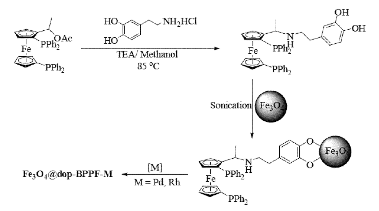
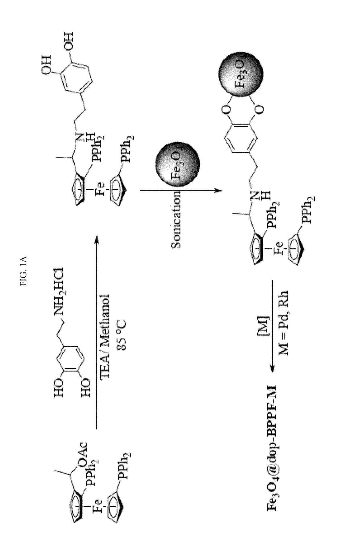
[0193]The syntheses of NN-dimethylferrocenyl ethyl amine (FA), N,N-dimethyl-1-[-1′,2-bis (diphenylphosphino)ferrocenyl] ethyl amine (BPPFA) and 1-[-1′,2-bis(diphenylphosphino)ferrocenyl]ethyl acetate (BPPFA-OAc) were performed according to previously reported procedures (G.-H. Hwang, E.-S. Ryu, D.-K. Park, S. C. Shim, C. S. Cho, T.-J. Kim, J. H. Jeong, M. Cheong, Organometallics 20 (2001) 5784-5787; and T. Hayashi, T. Mise, M. Fukushima, M. Kagotani, N. Nagashima, Y. Hamada, A. Matsumoto, S. Kawakami, M. Konishi, Bull. Chem. Soc. Japan 53 (1980) 1138-1151, each incorporated herein by reference in their entirety).

[0194]The synthesis involved the preparation of N,N-dimethyl-1-ferrocenylethylamine followed by dilithiation and reaction with chlorodiphenylphosphine to afford BPPFA (see FIG. 6) (T. Hayashi, K. Yamamoto, M. Kumada, Tetrahedron Lett. (1974) 4405-4408, incorporated herein by reference in i...

example 3

Characterization of the Synthesized Complex, Functionalized Magnetic Nanoparticle, and Catalyst

[0203]FIGS. 1B, 1C, 1D, and 1E are the transmission electron micrographs of Fe3O4, Fe3O4@dop-BPPF, Fe3O4@dop-BPPF-Pd, and Fe3O4@dop-BPPF-Rh, respectively. The micrographs show that the nanoparticles are spherically-shaped and uniformly distributed. The average diameter was 6-8 nm. The high-resolution transmission electron micrograph and selected area electron diffraction (SAED) image are shown in FIGS. 1F and 1G, respectively. The interplanar distance was determined to be consistent with the literature data (T. Rajh, L. X. Chen, K. Lukas, T. Liu, M. C. Thurnauer, D. M. Tiede, J. Phys. Chem, B 106 (2002) 10543-10552, incorporated herein by reference in its entirety). The SAED data also revealed higher order crystallinity, which was further confirmed by the X-ray diffraction (XRD) signature of the nanomaterial. The peaks located at 30.22°, 35.70°, 43.10°, 53.40°, 57.10° and 63.20° indicate t...


PUM

PropertyMeasurementUnit
diameteraaaaaaaaaa
temperatureaaaaaaaaaa
pressureaaaaaaaaaa

Abstract

A functionalized magnetic nanoparticle including an organometallic sandwich compound and a magnetic metal oxide. The functionalized magnetic nanoparticle may be reacted with a metal precursor to form a catalyst for various C—C bond forming reactions. The catalyst may be recovered with ease by attracting the catalyst with a magnet.

Description

RELATED APPLICATIONS[0001]This application claims the priority of the filing date of the U.S. Provisional Patent Application No. 62 / 406,449 filed Oct. 11, 2016, the disclosure of which is hereby incorporated herein by reference in its entirety.STATEMENT OF FUNDING ACKNOWLEDGMENT[0002]This project was funded by the National Plan for Science, Technology and Innovation (MAARIFAH)-King Abdulaziz City for Science and Technology through the Science and Technology Unit at King Fahd University of Petroleum and Minerals (KFUPM), the Kingdom of Saudi Arabia, award number 15-NAN4650-04.STATEMENT REGARDING PRIOR DISCLOSURES BY THE INVENTORS[0003]Aspects of this technology are described in an article “Magnetic nanoparticle-supported ferrocenylphosphine: a reusable catalyst for hydroformylation of alkene and Mizoroki-Heck olefination” by M. Nasiruzza an Shaikh, Md. Abdul Aziz, Aasif Helal, Mohamed Bououdina, Zain H. Yamania, and Tae-Jeong Kim, in RSC Advances, 2016, pages 41687-41695, which is in...

Claims


Application Information

Patent Timeline
Patent Type & Authority Applications(United States)
IPC IPC(8): C07F15/02C07C45/50C07C2/68B01J31/28B01J31/22B01J35/00B01J35/02
CPCC07F15/02C07C45/505C07C2/68B01J31/28B01J31/2295B01J2531/822B01J35/0013B01J35/023B01J2231/321B01J2531/842B01J2531/824B01J35/0033C07C41/30C07C201/12C07F17/02C07C45/50C07C2/861C07C17/269C07C2531/22C07C2531/28B01J37/343B01J23/745B01J23/8906B01J37/0203B01J31/1625B01J31/2414B01J2231/4261B01J2540/66A61B17/320758A61B2017/22038A61B2017/22079A61B2017/320775A61B2217/005C07C47/228C07C47/24C07C47/277C07C15/52C07C43/215C07C25/24C07C205/16C07C205/44A61B17/22A61B2017/00734
Inventor SHAIKH, M. NASIRUZZAMANAZIZ, MD. ABDULHELAL, AASIF
Owner KING FAHD UNIVERSITY OF PETROLEUM AND MINERALS
Why Eureka
Try Eureka