Solid Electrolytic Capacitor with Improved Performance at High Temperatures and Voltages

a technology of solid electrolytic capacitors and high temperature and voltage, which is applied in the manufacture of electrolytic capacitors, capacitor dielectric layers, fixed capacitor details, etc., can solve the problems of dcl, failure of conventional capacitors that employ in situ polymerized polymers, and significant deformation of capacitance of such materials at high temperatures

Active Publication Date: 2018-04-19
KYOCERA AVX COMPONENTS CORP
View PDF17 Cites 22 Cited by
  • Summary
  • Abstract
  • Description
  • Claims
  • Application Information

AI Technical Summary

Problems solved by technology

However, conventional capacitors that employ in situ polymerized polymers tend to have a relatively high leakage current (“DCL”) and fail at high voltages, such as experienced during a fast switch on or operational current spike.
While the PEDOT:PSS dispersions can result in some improved properties, the capacitance of such materials tends to significantly degrade at high temperatures, particularly when subjected to relatively high voltages.

Method used


Image

  • Solid Electrolytic Capacitor with Improved Performance at High Temperatures and Voltages
  • Solid Electrolytic Capacitor with Improved Performance at High Temperatures and Voltages
  • Solid Electrolytic Capacitor with Improved Performance at High Temperatures and Voltages

Examples


example 1

[0112]40,000 μFV / g tantalum powder was used to form anode samples. Each anode sample was embedded with a tantalum wire, sintered at 1410° C., and pressed to a density of 5.3 g / cm3. The resulting pellets had a size of 5.20×3.70×0.65 mm. The pellets were anodized to 49.0 volts in water / phosphoric acid electrolyte with a conductivity of 8.6 mS at a temperature of 85° C. to form the dielectric layer. The pellets were anodized again to 130 volts in a water / boric acid / disodium tetraborate with a conductivity of 2.0 mS at a temperature of 30° C. for 25 seconds to form a thicker oxide layer built up on the outside.

[0113]A conductive polymer coating was then formed by dipping the anodes into a dispersed poly(3,4-ethylenedioxythiophene) having a solids content 1.1% and viscosity 20 mPa·s (Clevios™ K, Heraeus). Upon coating, the parts were dried at 125° C. for 20 minutes. This process was repeated 10 times. Thereafter, the parts were dipped into a dispersed poly(3,4-ethylenedioxythiophene) hav...

example 2

[0114]Capacitors were formed in the manner described in Example 1, except that three (3) pre-coat layers were formed using a solution of (3-aminopropyl)trimethoxysilane in ethanol (1.0%). Multiple parts (450) of 47 μF / 20V capacitors were formed and encapsulated in a silica resin.

example 3

[0115]Capacitors were formed in the manner described in Example 1, except that three (3) pre-coat layers were formed using a solution of [3-(2-aminoethylamino)-propyl]trimethoxysilane in ethanol (1.0%).

[0116]Multiple parts (450) of 47 μF / 20V capacitors were formed as described in Examples 1-3 and encapsulated in a silica resin. The parts were tested for capacitance (CAP), “wet-to-dry” capacitance (W / D), dissipation factor (Df), ESR, and leakage current (DCL). The median results are set forth below in Table 1.

TABLE 1Electrical Properties1st DCL @2nd DCL @CAPW / DDfESR90 sec300 sec[μF][%][%][mohms][μA][μA]Example 144.2978.953.037.382.755.92Example 244.4379.201.348.477.2574.04Example 344.3579.061.256.31.160.38

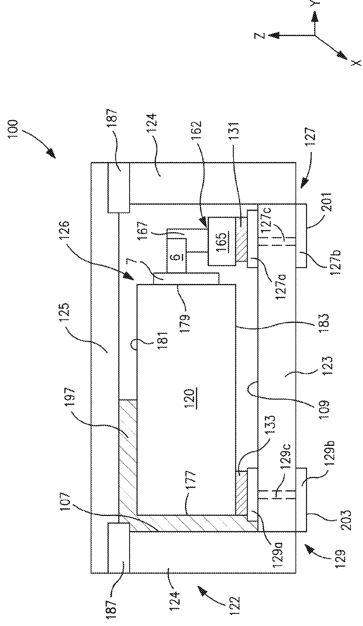
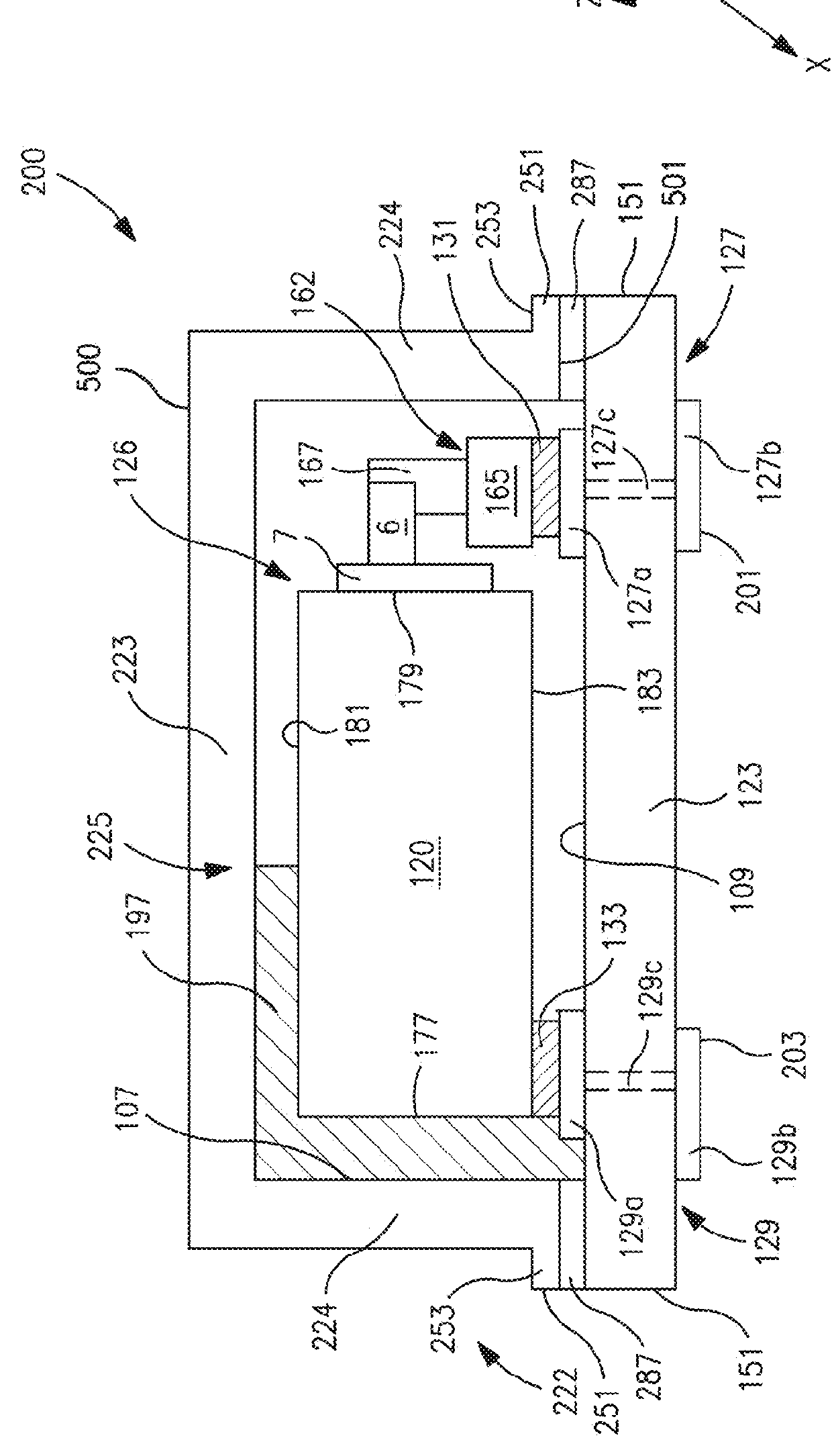
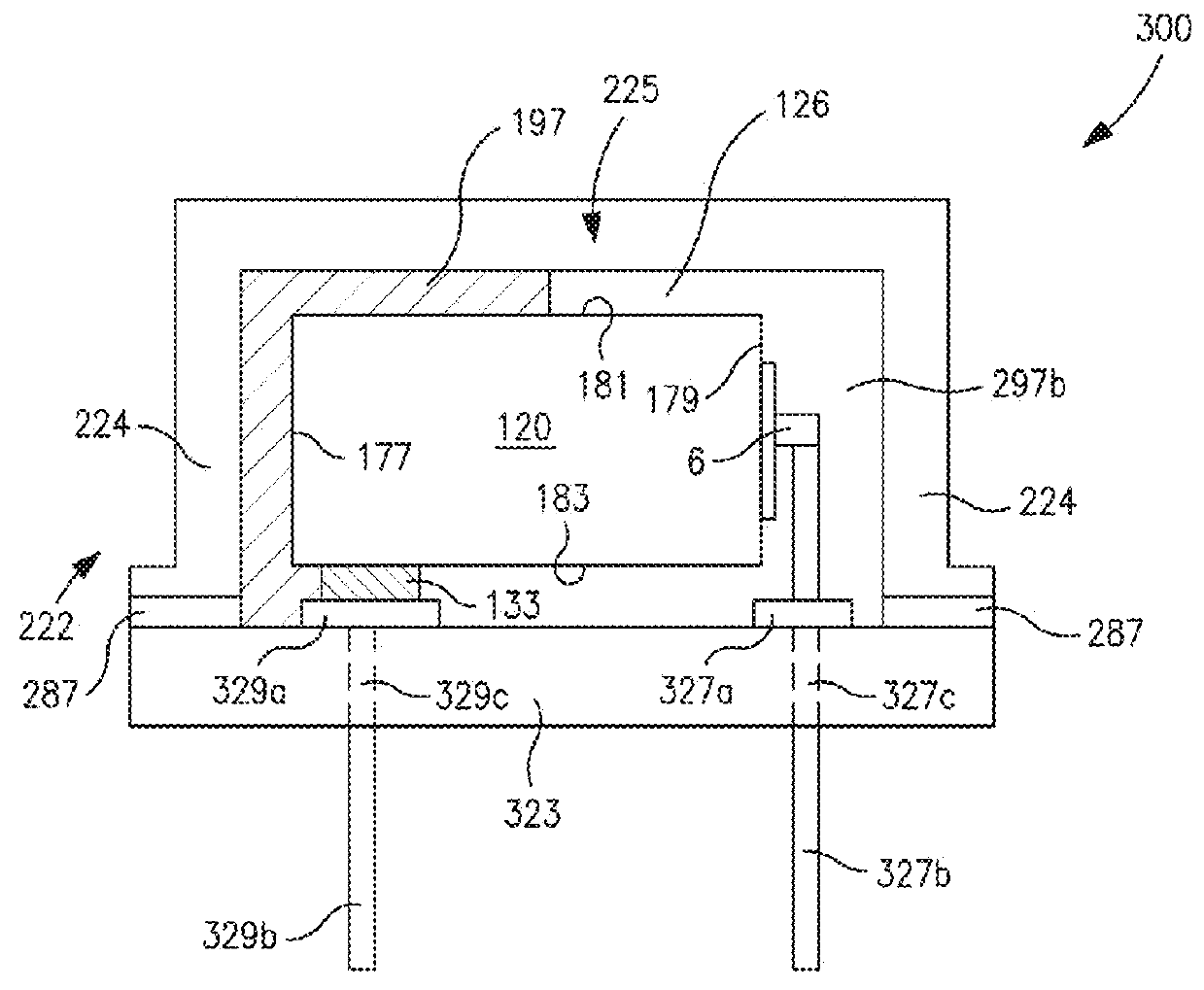
[0117]Multiple parts (10) of 47 μF / 20V capacitors (before encapsulation) were also formed as described in Examples 1-3 and dried at 150° C. for 4 hours. The resulting parts were then placed into a ceramic housing purged with nitrogen gas, and then hermetically sealed by seam welding...


PUM

PropertyMeasurementUnit
temperatureaaaaaaaaaa

Abstract

A capacitor assembly that is capable of exhibiting good electrical properties even under a variety of conditions is provided. More particularly, the capacitor contains a capacitor element that includes a porous anode body that contains a valve metal compound, a dielectric that overlies the anode body and includes an oxide of the valve metal compound, a solid electrolyte that overlies the dielectric, wherein the solid electrolyte includes at least one conductive polymer layer that contains a sulfonyl ion, and an organofunctional silane that is bonded to the oxide of the dielectric and is capable of bonding to the sulfonyl ion of the conductive polymer layer.

Description

CROSS REFERENCE TO RELATED APPLICATION[0001]The present application claims filing benefit of U.S. Provisional Patent Application Ser. No. 62 / 409,425 having a filing date of Oct. 18, 2016, and which is incorporated herein by reference in its entirety.BACKGROUND OF THE INVENTION[0002]Solid electrolytic capacitors (e.g., tantalum capacitors) are typically made by pressing a metal powder (e.g., tantalum) around a metal lead wire, sintering the pressed part, anodizing the sintered anode, and thereafter applying a solid electrolyte. Intrinsically conductive polymers are often employed as the solid electrolyte due to their advantageous low equivalent series resistance (“ESR”) and “non-burning / non-ignition” failure mode. For example, such electrolytes can be formed through in situ chemical polymerization of a 3,4-dioxythiophene monomer (“EDOT”) in the presence of a catalyst and dopant. However, conventional capacitors that employ in situ polymerized polymers tend to have a relatively high l...

Claims


Application Information

Patent Timeline
Patent Type & Authority Applications(United States)
IPC IPC(8): H01G9/025H01G9/15H01G9/00H01G4/10
CPCH01G9/025H01G9/15H01G9/0032H01G9/0036H01G4/10H01G2009/0014H01G9/028H01B3/18H01G9/012H01G9/07
Inventor PETRZILEK, JANUHER, MILOSLAVHOFIREK, TOMAS
Owner KYOCERA AVX COMPONENTS CORP
Why Eureka
Try Eureka