Adaptive control method and equipment of arc swing in narrow gap welding

a control method and narrow gap technology, applied in the field of welding technologies, can solve the problems of inability to ensure that the arc constantly heats the side walls of the groove in uniform and effective ways, the width of the groove and the central position of the welding seam may change, and the difficulty of ensuring the height of the welding seam, etc., to achieve the effect of high detection sensitivity and detection precision, strong resistance to interference, and convenient us

Active Publication Date: 2018-05-31
JIANGSU UNIV OF SCI & TECH
View PDF4 Cites 10 Cited by
  • Summary
  • Abstract
  • Description
  • Claims
  • Application Information

AI Technical Summary

Benefits of technology

[0017]1) The width of the narrow gap groove is detected in real time in a non-contact manner by using an infrared camera, achieving desirable synchronization between a detection point and an arc position, high detection sensitivity and detection precision, and strong resistance against interference from welding spatter, welding fume, and arc light.
[0018]2) A bent conducting rod swing mechanism driven directly (or through a transmission pair) by a motor is employed, so that the arc has better directivity, control precision of an arc swing angle is higher, and meanwhile, the design of a welding torch is simplified.
[0019]3) An image of a groove edge area away from the arc side is captured by using a small window and processed, which can e

Problems solved by technology

In an actual narrow gap welding process, affected by factors such as groove machining errors, workpiece assembly errors, and welding thermal deformation, the size of the groove width and central position of a welding seam may change.
As a result, even if new processes such as a swing arc welding method, a high-speed rotating arc welding method, and a snakelike welding wire welding method are used to control side wall penetration of the groove, it cannot be ensured that the arc constantly heats the side walls of the groove uniformly and effectively.
Meanwhile, it is also difficult to guarantee a stable welding seam height, thus affecting welding quality.
Disadvantages thereof are: 1) the wheel-type wire bending mechanism and the worm-gear swing mechanism are complex, and it is inconvenient to adjust a bending degre

Method used


Image

  • Adaptive control method and equipment of arc swing in narrow gap welding
  • Adaptive control method and equipment of arc swing in narrow gap welding
  • Adaptive control method and equipment of arc swing in narrow gap welding

Examples


embodiment 1

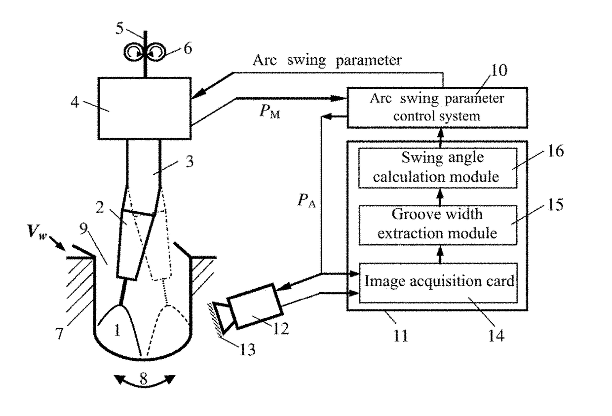
[0081]FIG. 8 is an embodiment diagram of method 1 of detecting the width of a narrow gap groove. Photographing conditions are as follows: the digital infrared CMOS camera 12 has a camera angle of γ=25° and an aperture of 16; the narrow bandpass filter has a central wavelength of 970 nm and a bandwidth of 25 nm; transmittance of the neutral dimmer glass is 10%. Welding conditions are as follows: flat-position direct-current MAG arc welding is employed, a welding current is 300 A, an arc voltage is 30 V, a welding speed is 20.3 cm / min, the welding torch standoff height: h=20 mm, a welding wire diameter is 1.2 mm, welding shield gases are Ar+20% of CO2 at a rate of 30 L / min, a groove width of I-type narrow gap mild steel welding is 13 mm, and a welding seam centring state is maintained during welding. Arc swing process parameter conditions are as follows: a swing frequency f=2.5 Hz, a swing radius r=8.5 mm, a bending angle of the bent conducting rod 3: β=8°, a swing angle αj=72°, stay ...

embodiment 2

[0084]FIG. 9 is an embodiment diagram of method 2 of extracting the width of a narrow gap groove. Photographing conditions and swing arc welding test conditions are the same as those in Embodiment 1. FIG. 9(a) is a welding image acquired by the computer image processing system 11 when the arc swings to the right side wall of the groove and starts to stay. To make the expression intuitive, two white-line small windows are used herein to represent positions of the mobile small windows 17 and 18 adaptively determined according to the highest point C2 of the arc area and changes in horizontal ordinate positions of the edge lines 19 and 20 of the groove. FIG. 9(b) is a morphological image of the arc after fixed threshold segmentation and morphological corrosion, position coordinates of the highest point C2 of the arc are extracted accordingly, and ordinate positions of the mobile small windows 17 and 18 are determined (as shown in FIG. 9(a)). For a global image after median filtering and...

embodiment 3

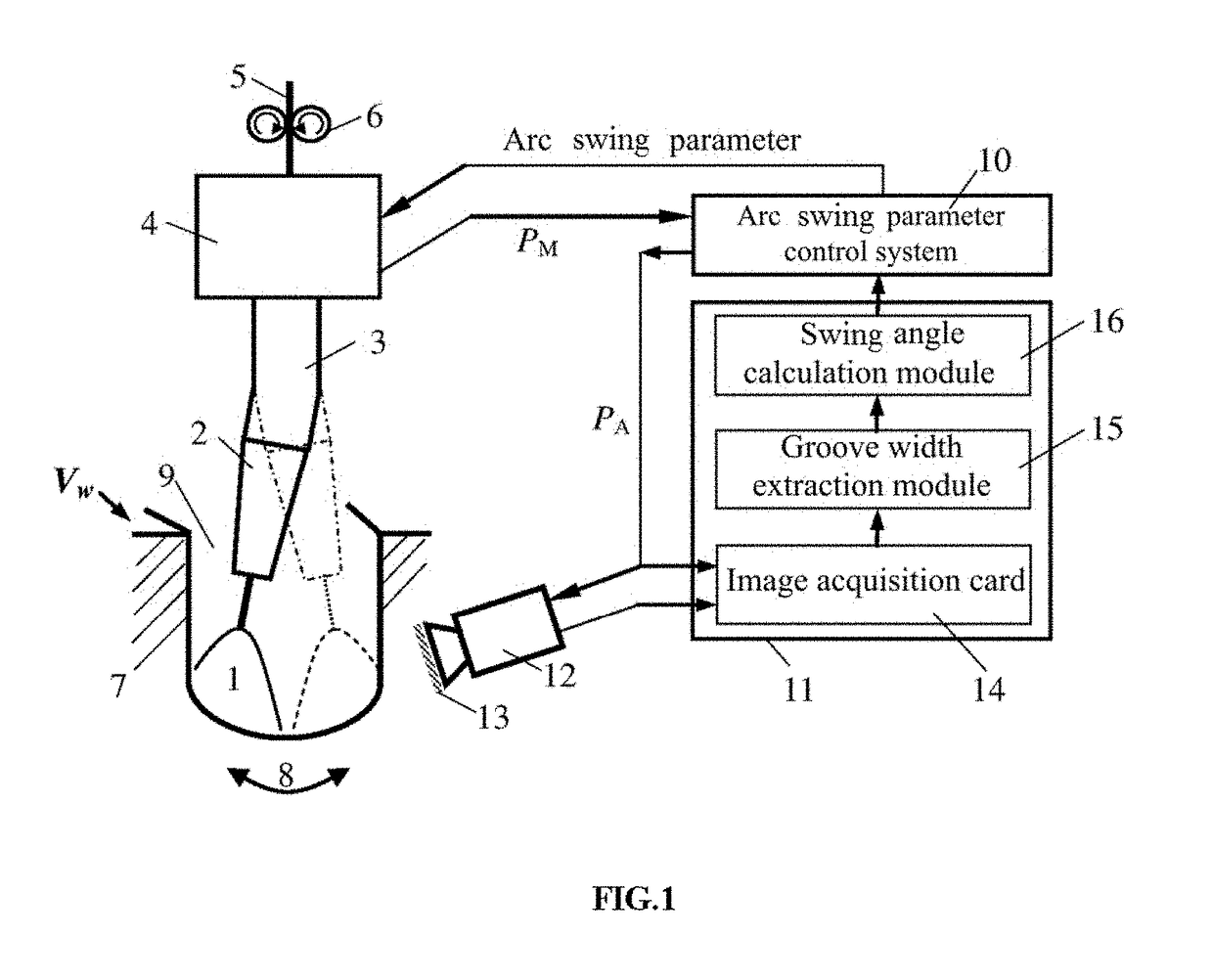
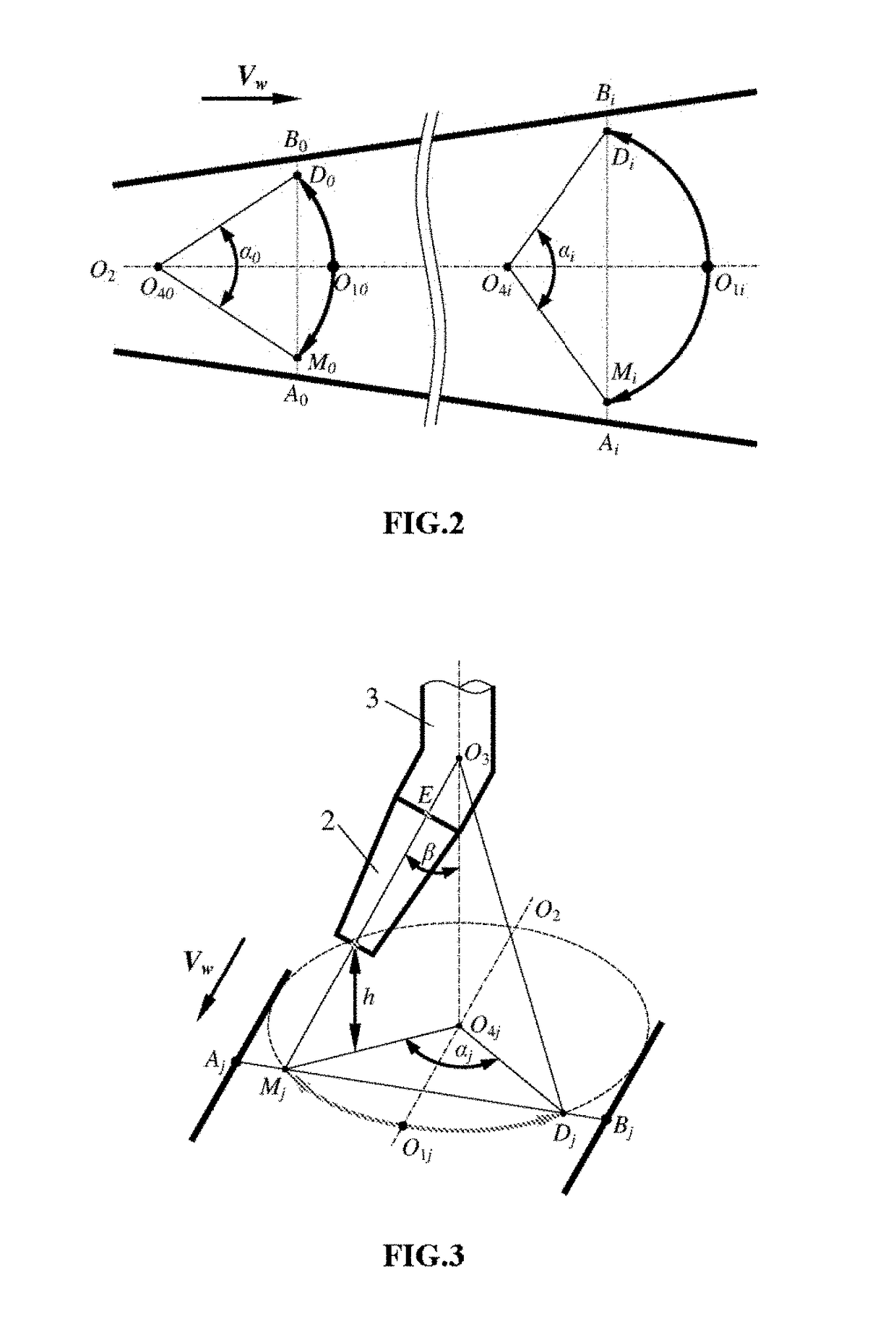
[0086]An embodiment of control for flat-position narrow gap welding arc swing is provided. With different arc swing radiuses, flat-position narrow gap welding arc swing control tests are conducted. Test conditions include: the preserved process gap g=2.0 mm, the swing frequency f=2.5 Hz, the stay duration on the side wall: ts=100 ms, a bending angle of the bent conducting rod 3: β=8°, and the groove width change determination threshold THw=0.2 mm; as the groove gap changes continuously in a range of 8 mm to 16 mm, the welding speed Vw correspondingly adjusts in a range of 30.4 cm / min to 15.2 cm / min automatically; other welding test conditions are the same as those in Embodiment 1.

[0087]In order to ensure the effectiveness of the arc swing control, when welding is performed using the minimum arc swing radius, at the maximum possible gap of the groove (that is, Gsi=Gmax), it should be ensured that in expression (4), arc swing angle αi≤180°. Therefore, before welding, the minimum radiu...


PUM

PropertyMeasurementUnit
Areaaaaaaaaaaa
Distanceaaaaaaaaaa

Abstract

Disclosed are an adaptive control method and equipment of arc swing in narrow gap welding. The control equipment is composed of an infrared camera system, a computer image processing system, an arc swing parameter control system, a bent-conducting-rod-type swing arc torch and the like. The infrared camera system acquires, in an external triggering manner, an infrared image of welding area when an arc is deviated towards the left or the right side wall groove, extracts information about the width of the groove in real time after image processing by a computer, and calculates an arc swing angle target value. The arc swing parameter control system controls a motor drive mechanism to rotate a bent conducting rod, and drives the welding arc to conduct circular arc swing according to the swing angle target value, thereby realizing the adaptive control for the arc swing angle according to changes of the groove width.

Description

BACKGROUND OF THE INVENTION1. Field of the Invention[0001]The present invention relates to the field of welding technologies, and in particular, to a method and equipment for performing adaptive control on narrow gap welding arc movement in a condition of a variable groove width.2. Description of the Prior Art[0002]The narrow gap gas metal arc welding is an efficient, high-quality, and low-cost welding method. In an actual narrow gap welding process, affected by factors such as groove machining errors, workpiece assembly errors, and welding thermal deformation, the size of the groove width and central position of a welding seam may change. As a result, even if new processes such as a swing arc welding method, a high-speed rotating arc welding method, and a snakelike welding wire welding method are used to control side wall penetration of the groove, it cannot be ensured that the arc constantly heats the side walls of the groove uniformly and effectively. Meanwhile, it is also diffic...

Claims


Application Information

Patent Timeline
IPC IPC(8): B23K9/095B23K9/02B23K9/10B23K9/127
CPCB23K9/0953B23K9/0213B23K9/1087B23K9/1274B23K9/0956B23K9/022B23K9/164B23K9/173
Inventor WANG, JIAYOUZHU, JIESU, NAYANG, MAOSENLI, WENHANG
Owner JIANGSU UNIV OF SCI & TECH
Why Eureka
Try Eureka