
Aggregate of carbon nanotubes, carbon nanotube composite material, and carbon nanotube wire

Active Publication Date: 2018-06-21
FURUKAWA ELECTRIC CO LTD
View PDF1 Cites 6 Cited by
  • Summary
  • Abstract
  • Description
  • Claims
  • Application Information

AI Technical Summary

Benefits of technology

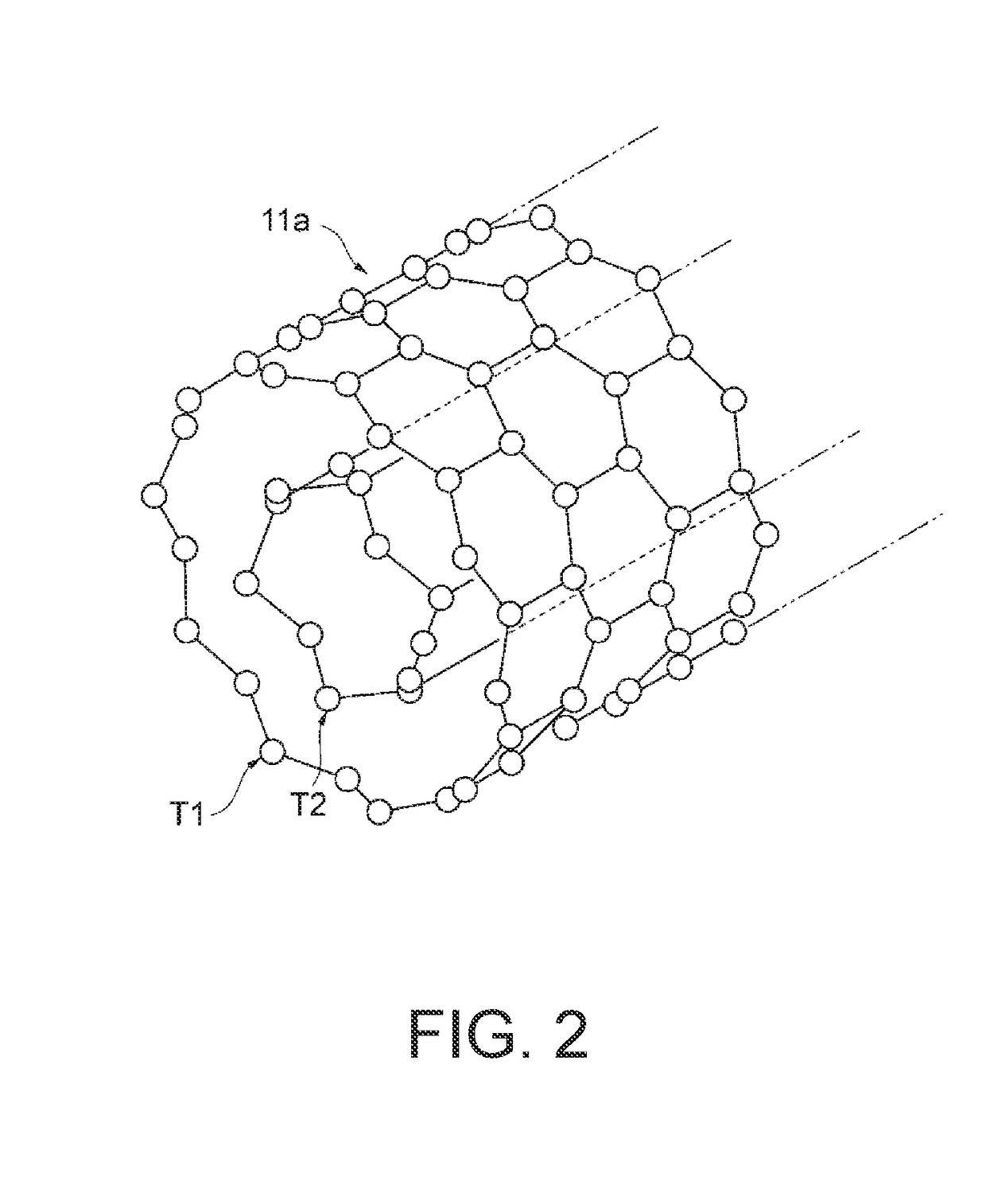
The present invention provides a carbon nanotube aggregate, composite material, and wire that have better electrical properties compared to conventional materials. The carbon nanotubes have a structure that allows for maximum doping effects and a reduced number of walls, resulting in lower resistance. The carbon nanotube composite material includes a carbon nanotube with one or more walls and a doping element that increases the amount of carriers contributing to conductivity, resulting in greater conductivity and improved electrical characteristics.

Problems solved by technology

In other words, compared to a resistivity of 1.68×10⁻⁶ Ω·cm for copper or a resistivity of 2.6×10⁻⁶ Ω·cm for aluminum, the resistivity of a carbon nanotube aggregate is higher by more than an order of magnitude, and thus, would not be a satisfactory substitute for copper or aluminum for use as a wire.

Method used


Image

  • Aggregate of carbon nanotubes, carbon nanotube composite material, and carbon nanotube wire
  • Aggregate of carbon nanotubes, carbon nanotube composite material, and carbon nanotube wire
  • Aggregate of carbon nanotubes, carbon nanotube composite material, and carbon nanotube wire

Examples


working examples

[0099]Below, working examples of the present invention will be explained. The present invention is not limited to the working examples below.

working examples 1-2

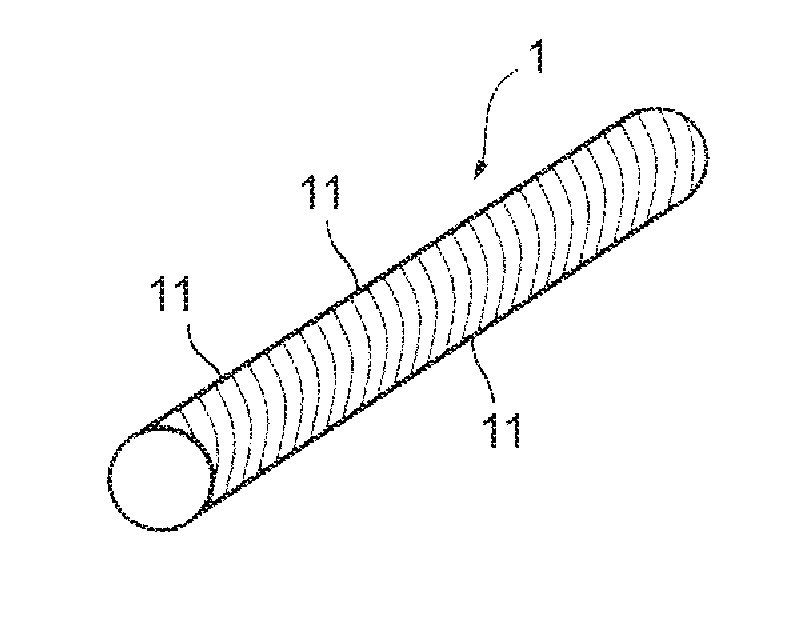
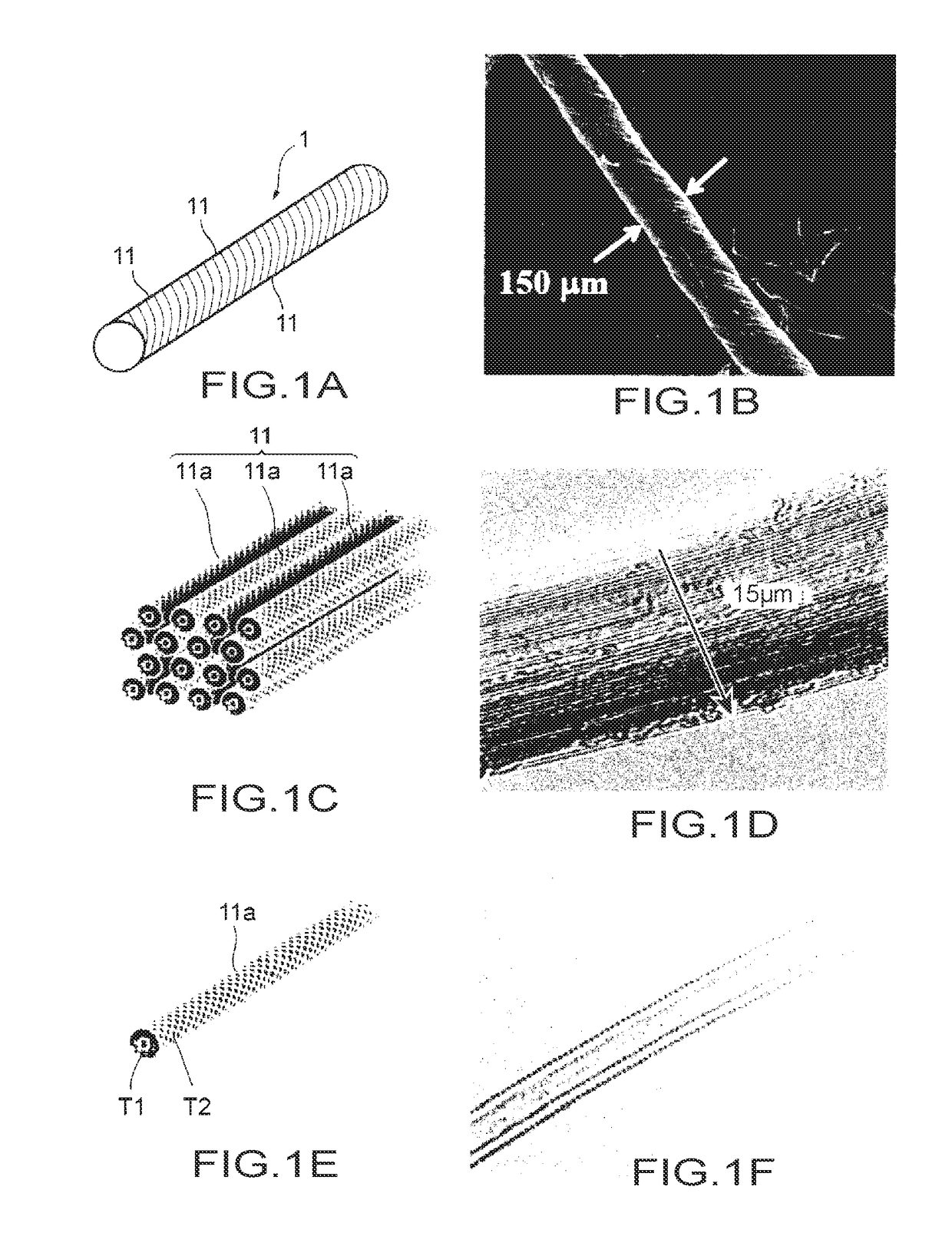
[0100]In a CNT manufacturing device as shown in FIG. 11, floating catalytic chemical vapor deposition (CCVD) was used such that a raw material solution L containing decahydronaphthalene as the carbon source, ferrocene as the catalyst, and thiophene as the reaction accelerator was provided by spraying into an alumina pipe 22 with an internal diameter Φ of 60 mm and a length of 1600 mm that was heated to 1300° C. by an electric furnace 21. As a carrier gas G, hydrogen was provided at 9.5 L / min. The CNT that was produced was collected in sheet form by a collector 23, and this sheet was wound and twisted to produce the CNT aggregate. Next, the CNT aggregate that was produced was heated to 500° C. in air, and then highly purified by performing acid treatment thereon. Then, nitric acid doping was performed on the highly purified CNT aggregate. A CNT aggregate with a diameter of approximately 180 μm as shown in FIG. 12A was attained.

[0101]Next, the structure and characteristics of the CNT ...

working examples 3-4

[0116]Next, a CNT aggregate produced by a similar manufacturing method to that of Working Example 1 was prepared, and the CNT aggregate was doped with iodine instead of the nitric acid, which was the dopant for Working Example 1. Also, in Working Example 4, aside from doping being performed with potassium, the CNT composite material was manufactured by the same method to Working Example 3.


PUM


Abstract

A low-resistivity carbon nanotube aggregate includes a plurality of carbon nanotubes each having one or more walls, wherein a ratio of a total number of carbon nanotubes that have two or three walls relative to a total number of said plurality of carbon nanotubes is 75% or greater, and wherein, in a G band of a Raman spectrum in the Raman spectroscopy of the plurality of carbon nanotubes, a G+ / Gtotal ratio that is indicative of an amount of semiconductor carbon nanotubes relative to metallic carbon nanotubes is 0.70 or greater.

Description

BACKGROUND OF THE INVENTIONTechnical Field[0001]The present invention relates to a carbon nanotube aggregate constituted of bundles having a plurality of carbon nanotubes, a carbon nanotube composite material, and a carbon nanotube wire, and in particular relates to a carbon nanotube aggregate constituted of carbon nanotubes for performing doping, a carbon nanotube composite material having a doping element that is different from carbon in the carbon nanotubes, and a carbon nanotube wire formed by bundling carbon nanotube aggregate or carbon nanotube composite material.Background Art[0002]Conventionally, electric lines constituted of a core wire made of one or more wires and an insulating cover that covers that core wire have been used as power lines or signal lines in various areas such as automobiles and industrial equipment. As materials forming the wire that constitutes the core wire, copper or a copper alloy is typically used from the perspective of electrical characteristics, ...

Claims


Application Information

Patent Timeline
IPC IPC(8): C01B32/16H01L51/00B82Y40/00B82Y30/00
CPCC01B32/16H01L51/0048B82Y40/00B82Y30/00H01L51/002H01B1/04C01B2202/06C01B2202/22C01B2202/34C01B2202/36C01B32/158C01B32/168H10K71/30H10K85/221
Inventor WATANABE, MASASHIGEAIZAWA, HIDEKIMIYOSHI, KAZUTOMIYAMASHITA, SATOSHIKAZAMA, YOSHINORITANIMURA, YUUDAIFUJIMURA, KOJIENDO, MORINOBUTAKEUCHI, KENJIFUJISHIGE, MASATSUGU
Owner FURUKAWA ELECTRIC CO LTD
Learn More