Photo-Acoustics Sensing Based Laser Vibrometer for the Measurement of Ambient Chemical Species

a laser vibrometer and photoacoustics technology, applied in the field of detection and analysis of pressure waves, can solve the problems of affecting the sensitivity of the diaphragm assembly in detecting the incoming pressure wave, adding weight to the assembly, and altering/limiting the resultant frequency respons

Inactive Publication Date: 2018-10-11
NASA
View PDF6 Cites 9 Cited by
  • Summary
  • Abstract
  • Description
  • Claims
  • Application Information

AI Technical Summary

Benefits of technology

[0009]One aspect of the present invention is a laser vibrometer capable of detecting and displaying pressure waves from acoustic signals that are generated by a chemical species via photoacoustic effect due to its excition by a laser whose wavelength coincides with an absorption feature. The laser vibrometer comprises a laser configured to produce a beam of monochromatic light, and a beam splitter that is configured to split the beam of monochromatic light into a reference beam and a sensing beam. The reference beam is directed to a photosensor. The laser vibrometer also includes a pressure-sensing diaphragm having a first side which when impacted by the pressure waves responsively vibrates, and a second side having a mirror-like surface finish. The sensing beam is directed against the second side of the pressure sensing diagram. The sensing beam may be reflected therefrom to an optional reflective mirror assembly. The mirror assembly is configured to reflect the sensing beam back against the pressure sensing diaphragm. The sensing beam is then directed to the photosensor. The photosensor is a photo-EMF sensor, which homodynes the sensing beam with the reference beam to output an analog signal whose phase modulation is proportional to the displacement of the diaphragm caused by the incident pressure wave. A displacement of the diaphragm as small as approximately 10 femtometers or less can be detected. The laser vibrometer may include a display that is configured to display the analog signal.

Problems solved by technology

Unfortunately, such auxiliary mechanical parts add significant weight to the assembly, and alter / limit the resultant frequency response towards the lower end.
Furthermore, such added weight also negatively impacts the sensitivity of the diaphragm assembly in detecting the incoming pressure waves, e.g., acoustic waves, due to the fact that such mechanical parts have innate inertia which can only be overcome by larger amplitude pressure waves, to move and generate detectable output signals.
In such approaches, the detection sensitivity is very limited due in part to the fact that the aperture of optical fiber is generally very limited, especially for the single-mode fiber that is needed for the said fiber-optic microphones to avoid the generation of higher order modes that would diminish the detected signal output.
This means that the probe light beam can only interrogate the pressure-sensing interface once and hence no possibility of further boosting up the detected signal strength.
In general, optical microphones suffer from limited sensitivity and scalability of output which limits their applicability to analysis of such weak signals.
This limited sensitivity results from use of optical interferometers for the detection mechanism, wherein the wavelength of the light beam involved is used as a gauge to monitor the scale of movement of the pressure-sensing diaphragm.
Because the optical light sources have a wavelength of approximately 1 micrometer, it becomes increasingly difficult to detect diaphragm movements in scales smaller than 1 nanometer (10−9 meter).

Method used


Image

  • Photo-Acoustics Sensing Based Laser Vibrometer for the Measurement of Ambient Chemical Species
  • Photo-Acoustics Sensing Based Laser Vibrometer for the Measurement of Ambient Chemical Species
  • Photo-Acoustics Sensing Based Laser Vibrometer for the Measurement of Ambient Chemical Species

Examples


Embodiment Construction

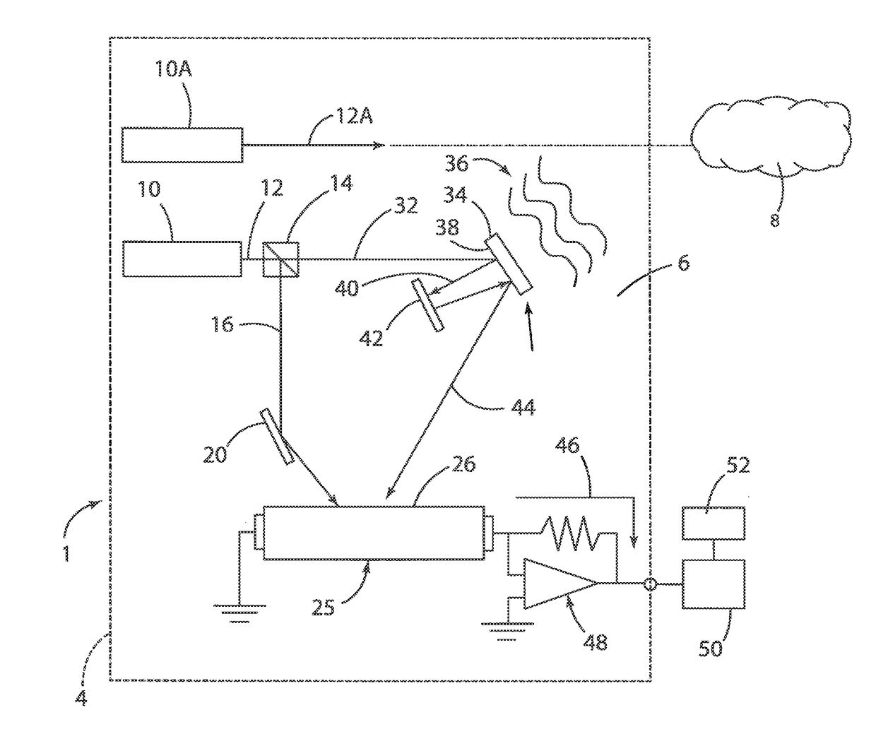
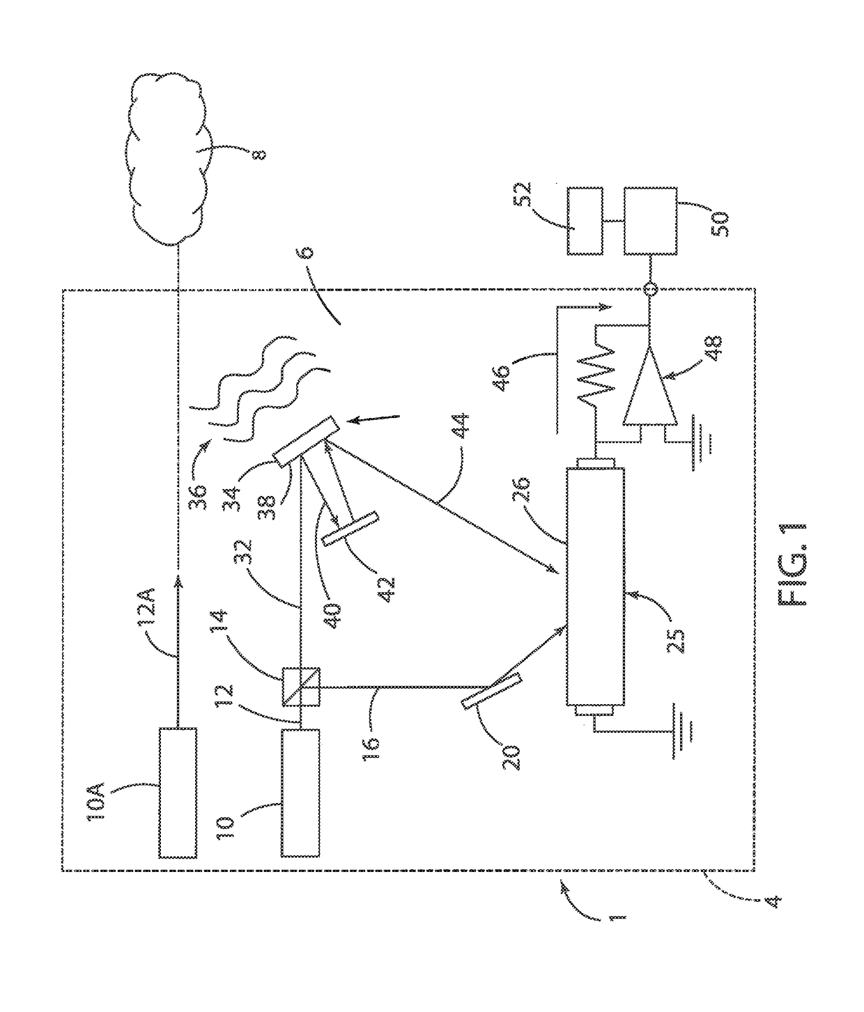
[0024]For purposes of description herein, the terms “upper,”“lower,”“right,”“left,”“rear,”“front,”“vertical,”“horizontal,” and derivatives thereof shall relate to the invention as oriented in FIG. 1. However, it is to be understood that the invention may assume various alternative orientations and step sequences, except where expressly specified to the contrary. It is also to be understood that the specific devices and processes illustrated in the attached drawings, and described in the following specification, are simply exemplary embodiments of the inventive concepts defined in the appended claims. Hence, specific dimensions and other physical characteristics relating to the embodiments disclosed herein are not to be considered as limiting, unless the claims expressly state otherwise.

[0025]With reference to FIG. 1, a laser vibrometer 1 according to one aspect of the present invention includes a light source such as a laser 10. Laser 10 can be either a continuous or a pulsed laser,...


PUM

PropertyMeasurementUnit
wavelengthaaaaaaaaaa

Abstract

A laser vibrometer for measurement of ambient chemical species includes a laser that produces a beam that is split into a reference readout beam and a signal readout beam. A probe laser beam is tuned to an absorption feature of a molecular transition, and generates acoustic signals when incident on a gaseous species via the photo acoustic effect. The scattered acoustic signals are incident on a thin membrane that vibrates. The readout laser beam reflected from the vibrating membrane is mixed with the reference beam at the surface of a photo-EMF detector. Interferrometric fringes are generated at the surface of the photo-EMF detector. Electric current is generated in the photo-EMF detector when the fringes are in motion due to undulations in the signal readout beam imparted by the vibrating membrane. A highly sensitive photo-EMF detector is capable of detecting picoJoules or less laser energy generated by vibrating processes.

Description

CROSS-REFERENCE TO RELATED PATENT APPLICATION[0001]This patent application claims the benefit of priority and is a continuation-in-part of U.S. patent application Ser. No. 14 / 584,004, filed on Dec. 29, 2014 which claims the benefit of priority to U.S. Provisional Patent Application No. 61 / 920,900, filed on Dec. 26, 2013. This application also claims the benefit of priority to U.S. Provisional Patent Application No. 62 / 534,739, filed on Jul. 20, 2017. The contents of the foregoing applications are hereby incorporated by reference in their entirety.STATEMENT REGARDING FEDERALLY SPONSORED RESEARCH OR DEVELOPMENT[0002]The invention described herein was made by employees of the United States Government and may be manufactured and used by or for the Government of the United States of America for governmental purposes without the payment of any royalties thereon or therefore.BACKGROUND OF THE INVENTION[0003]Vibrometer technology involves the detection and analysis of pressure waves, such a...

Claims


Application Information

Patent Timeline
Patent Type & Authority Applications(United States)
IPC IPC(8): G01N21/17G01N29/24G01N29/46G01N21/39G01N21/31
CPCG01N21/1702G01N21/39G01N29/2418G01N29/46G01N2021/1704G01N2021/1761G01N2021/3125G01N2021/3185G01N21/45G01N2201/0221G01N2291/0255
Inventor PRASAD, NARASIMHA S.
Owner NASA
Why Eureka
Try Eureka