Metal-clad laminate and metal foil with resin

a metal foil and metal-clad technology, applied in the field of metal-clad laminates and metal-clad foils with resin, can solve the problems of transmission loss caused by a conductor or a dielectric member, and achieve the effect of reducing transmission loss, excellent heat resistance and transmission characteristics, and less likely to increase transmission loss

Active Publication Date: 2018-10-18
PANASONIC INTELLECTUAL PROPERTY MANAGEMENT CO LTD
View PDF4 Cites 5 Cited by
  • Summary
  • Abstract
  • Description
  • Claims
  • Application Information

AI Technical Summary

Benefits of technology

[0016]According to the present disclosure, it is possible to provide a metal-clad laminate and a metal foil with resin having excellent heat resistance and transmission characteristics, capable of reducing a transmission loss (transmission loss is less likely to increase) even in transmission of a high frequency signal.

Problems solved by technology

However, there has been a problem that a transmission loss due to a conductor or a dielectric member occurs when a conductor circuit transmits a high frequency signal.

Method used


Image

  • Metal-clad laminate and metal foil with resin
  • Metal-clad laminate and metal foil with resin
  • Metal-clad laminate and metal foil with resin

Examples


examples

[0114]First, a modified polyphenylene ether copolymer was synthesized. An average number of phenolic hydroxyl groups at a molecular terminal per one molecule of polyphenylene ether is indicated as a number of terminal hydroxyl groups.

[Synthesis of Modified Polyphenylene Ether 1 (Modified PPE1)]

[0115]A polyphenylene ether and chloromethylstyrene were reacted to obtain modified polyphenylene ether 1 (modified PPE1).

[0116]Specifically, in a 1 L three-neck flask equipped with a temperature controller, a stirrer, a cooling installation, and a dropping funnel, 200 g of polyphenylene ether (polyphenylene ether having a structure shown in formula (5), SA90 manufactured by SABIC Innovative Plastics, intrinsic viscosity (IV) 0.083 dl / g, number of terminal hydroxyl groups 1.9, weight average molecular weight Mw 2000), 30 g of a mixture of p-chloromethylstyrene and m-chloromethylstyrene in a mass ratio of 50:50 (chloromethylstyrene:CMS, manufactured by TOKYO CHEMICAL INDUSTRY CO., LTD.), 1.227 ...

example 6

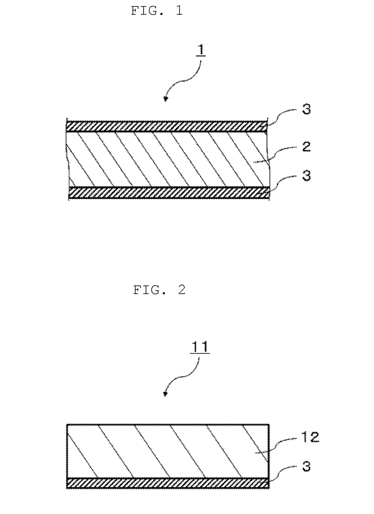
[0154]Using the resin varnish, a copper foil with resin (RCC) was prepared. The resin varnish was applied on a copper foil so that cured resin varnish gave a thicknesses of 130 μm, and dried by heating at 130° C. for 3 minutes until the resin varnish became a half-cured state, to give RCC.

[0155]The laminate for evaluation and RCC prepared as described above were evaluated by methods described below.

[Dielectric Characteristics (Relative Dielectric Constant (Dk) and Dielectric Dissipation Factor (Df))]

[0156]A relative dielectric constant and a dielectric dissipation factor of each substrate for evaluation (copper-clad laminate and RCC obtained in the above) at 10 GHz were measured by the cavity resonator perturbation method. Specifically, a relative dielectric constant and a dielectric dissipation factor of the substrate for evaluation were measured at 10 GHz with use of a network analyzer (N5230A manufactured by Agilent Technologies).

[Transmission Characteristics (15 GHz)]

[0157]First...


PUM

PropertyMeasurementUnit
average roughnessaaaaaaaaaa
relative dielectric constantaaaaaaaaaa

Abstract

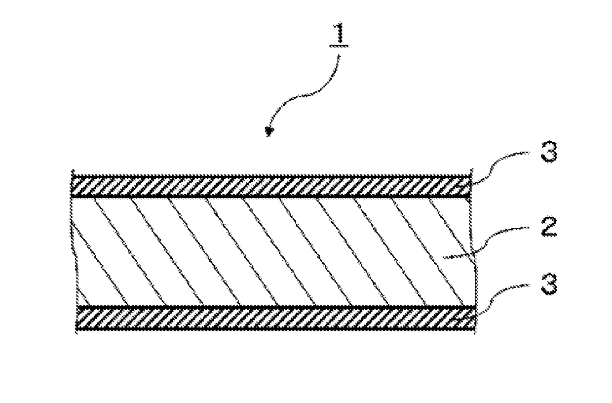
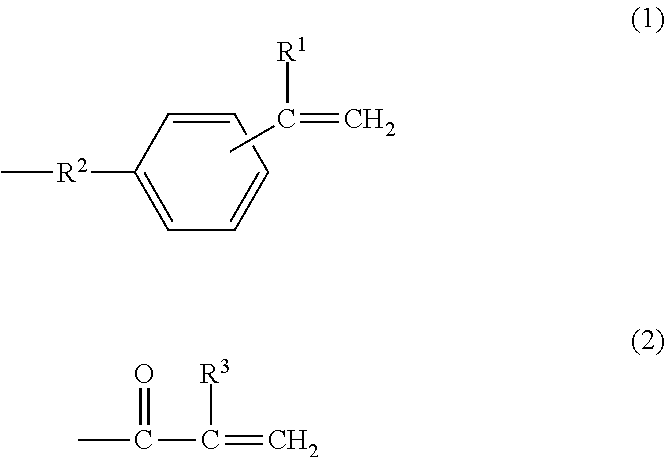
A metal-clad laminate includes an insulating layer including a cured product of a resin composition, and a metal foil disposed on a principal surface of the insulating layer. The resin composition includes a polyphenylene ether copolymer and a thermosetting curing agent, the polyphenylene ether copolymer having an intrinsic viscosity measured in methylene chloride at 25° C. of between 0.03 dl/g and 0.12 dl/g, inclusive. And the polyphenylene ether copolymer has, at a molecular terminal, a group represented by formula (1) or formula (2) at an average number of 1.5 to 3 per one molecule. Further, the metal foil has a first surface that is in contact with the insulating layer, the first surface having a 10-point average roughness (Rz) of 2.0 μm or less. And the metal foil includes a barrier layer disposed at a side of the first surface, the barrier layer containing cobalt.

Description

RELATED APPLICATIONS[0001]This application is a continuation of the PCT International Application No. PCT / JP2016 / 005133 filed on Dec. 15, 2016, which claims the benefit of foreign priority of Japanese patent application No. 2016-005261 filed on Jan. 14, 2016, the contents all of which are incorporated herein by reference.BACKGROUND1. Technical Field[0002]The present disclosure relates to a metal-clad laminate and a metal foil with resin.2. Description of the Related Art[0003]In recent years, along with an increase in amount of information to be processed, mounting techniques involving, for example, high integration of a semiconductor device to be incorporated, high density of wiring, and multi-layering are rapidly developing in various electronic devices.[0004]Recently, a printed wiring board compatible with high-frequency waves, such as a substrate for a millimeter-wave radar which is for in-vehicle use, is also required. However, there has been a problem that a transmission loss d...

Claims


Application Information

Patent Timeline
Patent Type & Authority Applications(United States)
IPC IPC(8): B32B15/08B32B27/28B32B27/26B32B5/02B32B17/06H05K1/03H05K1/09H05K1/02
CPCB32B15/08B32B27/285B32B27/26B32B5/02B32B17/067H05K1/0366H05K1/09H05K1/024H05K1/0242B32B2307/204B32B2250/03B32B2250/40B32B2262/101B32B2457/00H05K2201/0338H05K2201/0355B32B2260/021B32B2260/046B32B2307/3065B32B2307/306B32B2255/205B32B15/20B32B2307/732B32B2457/08B32B15/14B32B2307/538B32B2250/05B32B5/26B32B2255/06
Inventor KITAI, YUKIIRIFUNE, AKIRAINOUE, YUKITOKUDA, YUKI
Owner PANASONIC INTELLECTUAL PROPERTY MANAGEMENT CO LTD
Why Eureka
Try Eureka