Dual-loop self-injection locked optoelectronic oscillator

a self-injection and optoelectronic technology, applied in the field of photonic and optoelectronic oscillators, can solve the problems of increased phase noise, increased cost of ultra narrow bandwidth rf filter, and drawbacks of the standard oeos developed, etc., to achieve high rf frequency stability, improve performance, and ultra-low phase noise levels

Inactive Publication Date: 2018-11-15
VIKULIN ALEXANDER
View PDF0 Cites 9 Cited by
  • Summary
  • Abstract
  • Description
  • Claims
  • Application Information

AI Technical Summary

Benefits of technology

[0009]The present subject matter relates generally to photonic and optoelectronic oscillators of improved performance providing high RF frequency stability and ultralow levels of phase noise. The present disclosure can find application in a wide variety of fields, wherever signal generation is required at high respective frequencies with reduced noise, such as high frequency communication, radars, metrology, navigation, timing, and global position. OEO generated signals may be used as carriers and are important in clock recovery, and in communication broadcasting and receiving.

Problems solved by technology

However, there are some drawbacks of the standard OEOs developed in early years.
Second, it is costly to make an ultra narrow bandwidth RF filter which is required when the optical delay line (the fiber length) is long.
And third, the additional loss from the RF filter decreases the cavity Q of the optoelectronic oscillator, which results in an additional increase in the phase noise.
Spurious components separated by multiples of formula (1) deteriorate the performance of an OEO having a single optical fiber.

Method used


Image

  • Dual-loop self-injection locked optoelectronic oscillator
  • Dual-loop self-injection locked optoelectronic oscillator
  • Dual-loop self-injection locked optoelectronic oscillator

Examples


Embodiment Construction

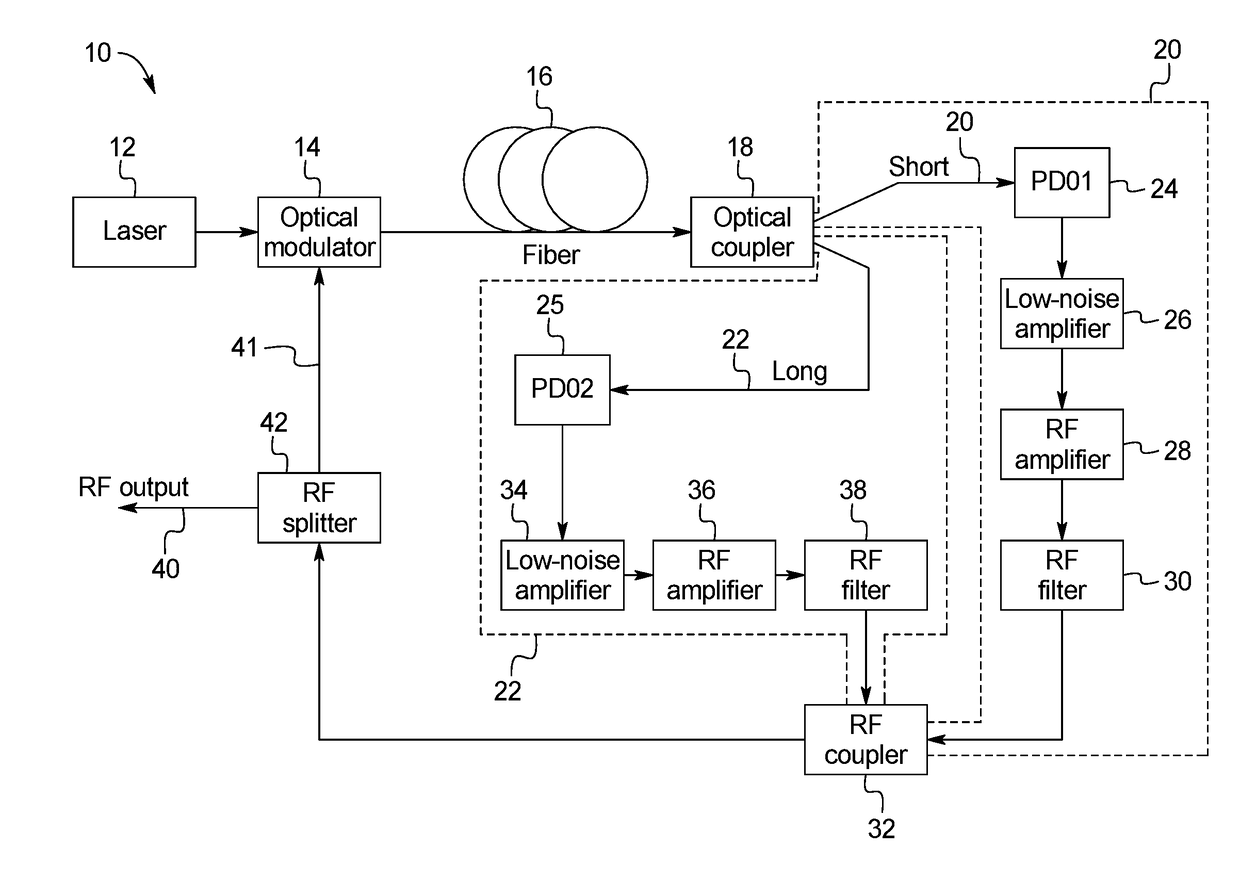
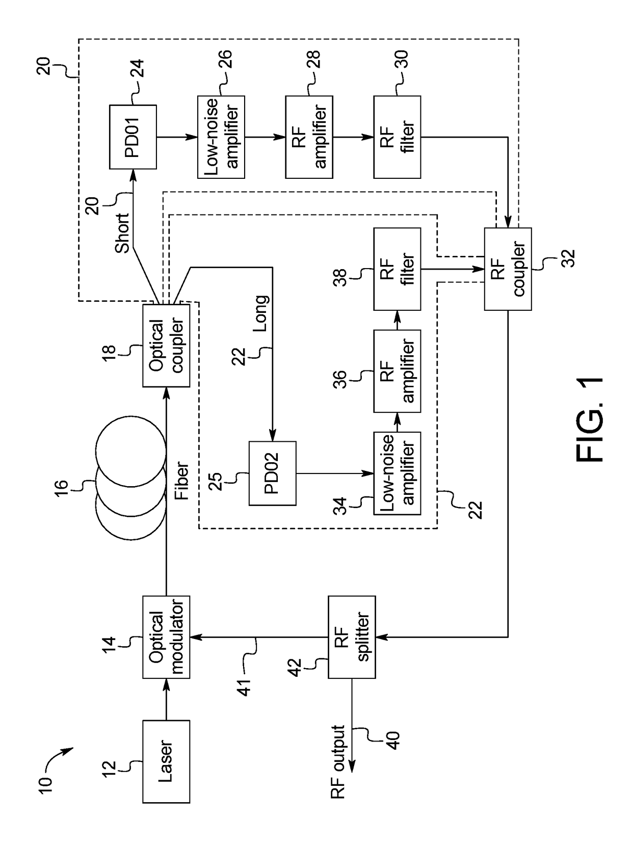
[0028]With reference to FIG. 1, an example of the present OEO system 10 includes a continuous wave laser 12 having its output connected as an input signal to an optical modulator 14. Any suitable laser 12 emitting in visible or invisible parts of the spectrum may be used. The optical modulator 14 may be of any conventional construction, such as a Mach-Zehnder modulator or an electro-absorption modulator. A basic feature of the modulator 14 is that it has both DC bias and RF input ports. The output optical signal from the optical modulator is a continuous optical wave modulated at the frequency of the RF signal applied to the modulation port. The output from the optical modulator 14 is coupled to an optical fiber 16 having a high value of Q. The fiber 16 may be a single mode fiber or a multi-mode one. The length of the optical fiber 16 is chosen to ensure the necessary high Q for the oscillator in order to achieve the required phase noise level. In practice, a length of several kilom...


PUM

PropertyMeasurementUnit
lengthaaaaaaaaaa
opticalaaaaaaaaaa
temperatureaaaaaaaaaa

Abstract

The present disclosure provides a dual loop self injection locked optoelectronic oscillator having a single fiber in its both loops which generates a high Q microwave output signal with a very low phase noise and spurious harmonics levels. The circuit may comprise an optical coupler having different lengths of the output arms and two electronic paths, which form two feedback loops of the oscillator. The circuit may comprise a single fiber with high Q, an optical circulator, and an optical coupler, which serves as a reflector, and two electronic paths which form two feedback loops of the oscillator.

Description

CROSS-REFERENCE TO RELATED APPLICATIONS[0001]This application incorporates by reference and claims the benefit of priority to U.S. Provisional Application 62 / 505,518 filed on May 12, 2017.BACKGROUND OF THE INVENTION[0002]The present subject matter relates generally to photonic and optoelectronic oscillators of improved performance providing high RF frequency stability and ultralow levels of phase noise.[0003]A variety of approaches can be used to obtain high spectral purity and low noise signals. For example, radio frequency (RF) and microwave oscillating signals may be generated by using various types of oscillators having energy storage elements. The quality factor Q, or the energy storage time, of an energy storage element inside an oscillator can determine the spectral linewidth of the respective oscillating signal. High quality factor Q or long energy storage time can be used to reduce the spectral linewidth of the oscillating signal and hence improve the signal spectral purity...

Claims


Application Information

Patent Timeline
Patent Type & Authority Applications(United States)
IPC IPC(8): G02F1/01
CPCG02F1/0123G02F2001/212G02F2/02H03B17/00G02F1/212
Inventor VIKULIN, ALEXANDER
Owner VIKULIN ALEXANDER
Why Eureka
Try Eureka